Download
1 / 49
520 likes | 849 Vues
Lectures 20 and 21 Propagation of electromagnetic waves in non-conducting materials. Introduction Previous lectures studied electromagnetic waves travelling in vacuum. We now extend this treatment to propagation in non-conducting materials.

E N D
Lectures 20 and 21 Propagation of electromagnetic waves in non-conducting materials
Introduction • Previous lectures studied electromagnetic waves travelling in vacuum. • We now extend this treatment to propagation in non-conducting materials. • In particular we will be interested in the propagation of waves from one media into a second different media (reflection and refraction effects).
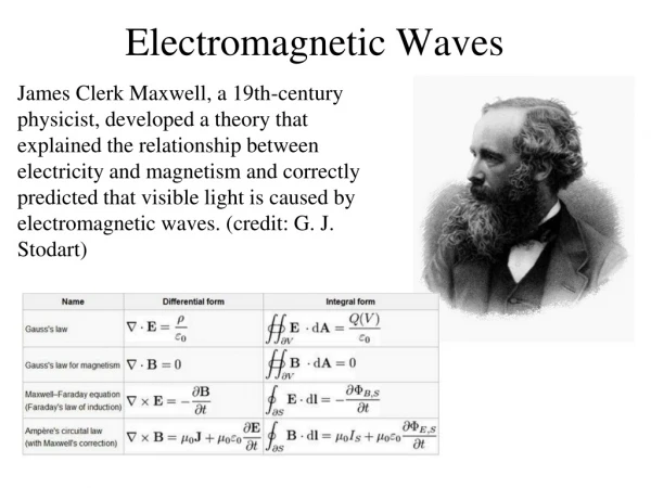
Summary of electromagnetic waves in vacuum • Maxwell's equations in a vacuum lead to wave equations for E and B. The resultant waves propagate with a velocity c=(00)-1/2. • E, B and the propagation direction are mutually perpendicular (TEM). • E and B are in phase and have amplitudes related by E=cB.
Propagation in LIH non-conducting media Propagation velocity and refractive index The treatment in this case parallels that in a vacuum except that we must replace 0 by 0rand 0 by 0r. Hence the speed of light in the medium, cm, is given by cm=1/(0r0r)1/2 = c/(rr)1/2 Where c is the speed of light in a vacuum.
However the only materials that have a r which is significantly different from 1 are non-LIH ones (e.g. iron). Hence for most LIH non-conducting materials cmc/(r)1/2. The refractive index n of a given material is defined as the speed of light in vacuum divided by that in the material. Hence n = c/cm = (rr)1/2 (r)1/2 or n2r
Because r always has a value greater than one, the speed of light in a material is always less than in a vacuum. As both r and n may vary strongly with frequency, discrepancies may arise when comparing values of r (often the static, DC value is used) with n2 (generally the value appropriate to optical frequencies).
Worked example r of the material of an optical fibre has values of 15 at 700 nm and 26 at 400 nm. If 700 and 400 nm light pulses are sent along the fibre what is the delay between their arrival at the far end (length of fibre is 6000 km)?
Relationship between E and B In vacuum E=cB. In a material this is modified toE=cmB=cB/n and because H=B/(0r)B/0 as r1 H=nE/(c0)
Worked example An electromagnetic wave, with an E-field of amplitude 1x10⁴ V/m, travels (i) in vacuum and (ii) in a medium with n=3. Calculate the amplitude of the B-field in both cases. If the wave has a frequency of 5x10¹⁴Hz what are the corresponding wavelengths for cases (i) and (ii)?
Reflection and refraction at the interface between two different materials The aim is to establish the properties of electromagnetic waves when they encounter a plane interface separating two different non-conducting materials (generally two different dielectrics). In particular equations will be derived which give the fractions of the incident wave which are reflected and transmitted at the interface.
Mathematical description of a plane wave not propagating along one of the principal axes So far we have only considered waves which propagate along one of the principal axes. For example a plane wave propagating along the x-axis is described by an equation of the form E=E0sin(kx-t), one propagating along the y-axis by E=E0sin(ky-t) etc. In the following we will need to consider plane waves which do not propagate along one of these principal axes. However we can always resolve the direction of the wave onto two or more of the principal axes.
The wave lies in the x/y-plane and propagates in a direction which makes an angle to the y-axis. There are hence components cos along the y-axis and sin along the x-axis. The equation for this plane wave is hence of the form E=E0sin(k(xsin+ycos)-t)
The wave vector, k, in the above equations is given by 2/ where is the wavelength of the wave. In addition if the wave propagates in a material with a velocity cm then =cmk=(c/n)k where is the angular frequency of the wave. Hence k=n/c
Boundary conditions for E, D, B and H at an interface • In the lectures on dielectrics and magnetic materials it was shown that, in the absence of free surface charge and conduction currents, the following boundary conditions existed for E, D, B and H • D and B: Normal components continuous • E and H: Tangential components continuous • These boundary conditions will be used below for electromagnetic waves incident at the boundary between two materials.
Frequency and direction of reflected and refracted waves In the figure below a plane electromagnetic wave travelling in a material of refractive index n1 is incident on the plane boundary with a second material of refractive index n2. The incident wave propagates at an angle i to the normal of the boundary and has E- and H-fields of magnitude Ei and Hi.
The E-field of the incident wave lies in the plane of incidence (the x/y-plane), this is known as the E parallel configuration. For this configuration the B- and H-fields must be normal to the plane of incidence.
In general there will be, in addition to the incident wave, a reflected wave at an angle r and a refracted or transmitted wave at an angle t. Each of these waves will have E- and H-fields as shown with amplitudes related by the expression H=nE/0c where n is the refractive index of the appropriate material.
The E-fields of the three waves are given by the following expressions Ei=Ei0sin(k1(xsini-ycosi)-1t) (A) Er=Er0sin(k1(xsinr+ycosr)-1t) (B) Et=Et0sin(k2(xsint-ycost)-2t) (C) Where Ei0, Er0 and Et0 are the amplitudes of the E-fields and k1 and k2 and 1 and 2 are the wavevectors and angular frequencies of the waves in the two materials.
The boundary condition for E requires that the tangential component (the component parallel to the boundary) be continuous. Hence if we evaluate this component on both sides of the boundary we must obtain the same result. The tangential component of each E-field is given by the magnitude of the E-field multiplied by cos, where is the appropriate angle. On the side of the boundary in material 1 the total tangential component of the E-field is the difference of the components due to the incident and reflected waves (see above figure). In material 2 there is only the transmitted wave.
Hence the requirement that the tangential component of the E-field be continuous can be written Eicosiy=0- Ercosry=0=Etcosty=0(D) Where y=0 indicates that the preceding expression is evaluated at the boundary y=0.
Substituting in (D) the expressions for Ei, Er and Etgiven by (A), (B) and (C) and evaluated for y=0 Ei0cosisin(k1xsini-1t)-Er0cosrsin(k1xsinr-1t)=Et0costsin(k2xsint-2t)(E) This equation must hold at all times and for all values of x. This is only possible if all the coefficients of x and all the coefficients of t are equal. This requires 1=2 and k1sini=k1sinr=k2sint
1=2 and k1sini=k1sinr=k2sint Hence The frequencies of the waves in the two materials are equal 1=2 The angles of incidence and reflection are equal k1sini=k1sinri=r
The incident and transmitted angles are related by k1sini=k2sint. However as k1=n11/c and k2=n22/c = k1=n21/c the expression k1sini=k2sint can be written as n1sini=n2sint. This is Snell’s law of refraction. The above results would have been obtained if E were polarized normal to the plane of incidence (H polarised parallel to the plane of incidence). These results hence apply to any incident wave.
Worked example A beam of light travelling in air (n=1) is incident on a plane interface of a dielectric with n=2.5 at an angle of 35. What angle to the normal does the refracted (transmitted) beam make?
Amplitudes of the reflected and refracted waves The above procedure provided information on the frequencies and directions of the incident, reflected and transmitted waves. The next step is to derive expressions which give their relative amplitudes.
Returning to equation (E) above, which is valid when E is parallel to the plane of incidence, the spatial and time dependent components have been shown to be equal. Hence (E) reduces to Ei0cosi - Er0cosi=Et0cost(F) Where r has been replaced by i.
In addition the tangential component of the H-field must be continuous at the boundary between the two materials. For the present case H is normal to the incident plane so that the tangential component of H is simply H. For the tangential component of H to be continuous we must therefore have Hi0+Hr0=Ht0 But H=nE/0c so the above can be written as n1Ei0+n1Er0=n2Et0(G)
Ei0cosi - Er0cosi=Et0cost(F) n1Ei0+n1Er0=n2Et0(G)
Equations (F) and (G) can now be used to eliminate either Er0 or Et0. Eliminating Et0: From (G)Et0=(Ei0+Er0)n1/n2 Substituting into (F) Ei0cosi-Er0cosi=(Ei0+Er0)(n1/n2)cost Ei0(cosi-(n1/n2)cost)=Er0(cosi+(n1/n2)cost) Multiplying through by n2 Ei0(n2cosi-n1cost)=Er0(n2cosi+n1cost)
(H) Now eliminating Er0. From (G) (I) r// and t//, which relate the amplitudes of the reflected and transmitted E-fields to that of the incident E-field, are known as the reflection and transmission coefficients for E parallel to the plane of incidence.
The polarisation of E can also be aligned normal to the plane of incidence (H is now parallel to the plane of incidence). The boundary conditions that the tangential components of E and H are continuous now require: Ei0+Er0=Et0 Hi0cosi-Hr0cosi=Ht0cost (J) (K)
The equation (H)-(K) are known as the Fresnel relationships or equations. The signs of these equations give the relative phases of the waves. If positive there is no phase change, if negative there is a phase change.
Properties of the Fresnel Equations The properties can be more easily seen if we consider a special case where one of the materials is air (n=1) and the other has a refractive index n. Consider the case where the wave is incident from air. Hence n1=1 and n2=n. The Fresnel equations become with sini/sint=n
For normal incidence (i=t=0) both r// and r and t// and thave the same magnitudes r//=r=(n-1)/(n+1), t//=t=2/(1+n) As i90 the magnitudes of the reflection coefficients tend to 1 (total reflection) and the magnitude of the transmission coefficients tend to zero (zero transmission).
For a certain angle B, known as the Brewster angle, r// becomes zero whereas r remains non-zero. For this angle light can only be reflected with E perpendicular to the plane of incidence. • If unpolarised light is incident at the Brewster angle then the reflected light will be polarised.
The Brewster angle is found by setting r//=0. ncosi=cost(L) In addition Snell’s law gives us nsint=sini(M) dividing (L) by (M) (ncosi)/(nsint)=cosi/sint=cost/sini
cosisini= costsint and hence sin2i=sin2t as 2sincos=sin2 The equality sin2i=sin2t implies that either i=t or i=90-t. The former can not be correct as we also must have nsint=sini and n1. Hence at the Brewster angle we must have i=90-t and Snell’s law becomes nsint=sinBnsin(90-B)=sinB
but sin(90-)=cos hence ncosB=sinB n=sinB/cosB=tanB
Worked Example Calculate the Brewster angle for glass with a refractive index of 1.55.
Waves propagating from a material into air We now have n1=n and n2=1. Fresnel’s equations have the form and nsini=sint In this case the equations for r// and r and for t// and t are interchanged compared to those for when the wave is incident from air.
However because nsini=sintt>i. For i equal to a certain value, the critical angle c, sintbecomes equal to unity and hence t=90. At this point both reflection coefficients become equal to one and the waves are totally reflected. As the value of sint can not exceed unity, for i>cthe reflection coefficients remain equal to unity. Hence for i>c all the incident light is reflected. This is known as ‘total internal reflection’. i=c occurs when sint=1. Hence nsinc=1sinc=1/n
Power reflection and transmission coefficients The reflection and transmission coefficients derived above give the amplitudes of the electric fields associated with the waves. However in general it is the power of the wave which is measured experimentally. From lecture 19 the power density of an electromagnetic wave is given by the Poynting vector N=ExH. This has a magnitude EH = nE2/(c0), using H=nE/(c0). Hence the energy density nE2
The coefficients which give the fraction of energy reflected or transmitted at a boundary between two materials equal the appropriate values of r2 or t2 with the inclusion of the appropriate value(s) of n. If R is the power reflection coefficient at an interface between a material of refractive index n1 and one of n2then where r is the appropriate reflection coefficient given by the Fresnel relationships. Similarly if T is the power transmission coefficient
Example: What are the reflection and transmission power coefficients for light incident normally from air into a material of refractive index n? i=t=0 and r//=r=(n-1)/(n+1) Hence t//=t=2/(n+1)
Worked Example A compound camera lens consists of 10 individual glass lenses. If the glass has a refractive index of 1.6 what fraction of any incident light is lost in reflections as the light passes through the compound lens. (Assume normal incidence).
Worked example What form do electromagnetic waves take in a conducting medium (0)?
Conclusions • Propagation velocity and refractive index • Relationship between E and Bin a material • Mathematical description of a plane wave not propagating along one of the principal axes • Frequency and direction of reflected and refracted waves • Amplitudes of the reflected and refracted waves: the Fresnel equations • Properties of the Fresnel equations • Brewster angle • Critical angle and total internal reflection • Power reflection and transmission coefficients