Download
1 / 35
350 likes | 594 Vues
Electromagnetic Waves and Their Propagation Through the Atmosphere. What are Electromagnetic Waves?. An electromagnetic wave is an energy wave produced from an electrical discharge. Electromagnetic waves have rise and fall cycles. The number of rise and fall cycles per second is its frequency.

E N D
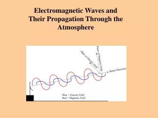
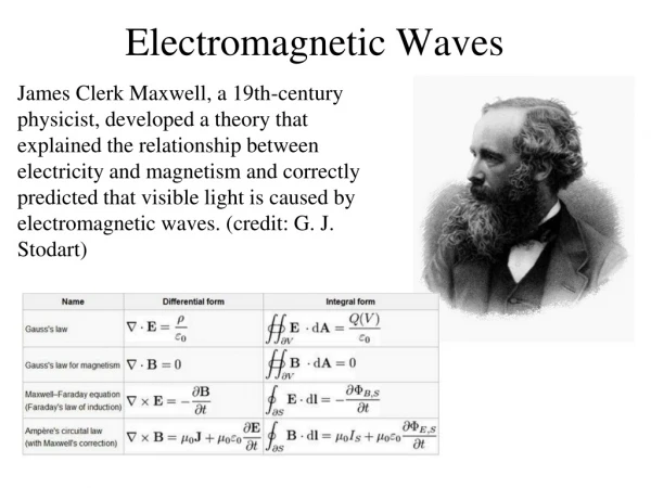
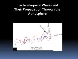
Electromagnetic Waves and Their Propagation Through the Atmosphere
What are Electromagnetic Waves? • An electromagnetic wave is an energy wave produced from an electrical discharge. • Electromagnetic waves have rise and fall cycles. • The number of rise and fall cycles per second is its frequency. • We can’t see or feel them, but they are around us.
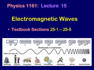
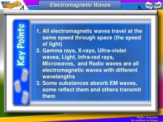
Gamma rays, X-rays, Ultra-violet waves, Light, Infra-red rays, Microwaves, and Radio waves are all electromagnetic waves with different wavelengths Some All electromagnetic waves travel at the same speed through space (the speed of light) Substances absorb EM waves, some reflect them and others transmit them
Electromagnetic waves: Interact with matter in four ways: Reflection: Refraction:
Scattering: Diffraction:
Electromagnetic Waves are characterized by: Wavelength, l [m, cm, mm, mm etc] Frequency, f [s-1, hertz (hz), megahertz (Mhz), gigahertz (Ghz) where: c = l f
DANGEROUS RADIATIONS • High doses of UV rays, X-rays and Gamma radiation can kill cells. Smaller doses can causes cells to become cancerous • X-rays and Gamma rays pass through soft tissues but some is absorbed by cells
Polarization of electromagnetic waves The polarization is specified by the orientation of the electromagnetic field. The plane containing the electric field is called the plane of polarization.
Earth curvature Electromagnetic ray propagating away from the radar will rise above the earth’s surface due to the earth’s curvature.
Electromagnetic Wave Summary • Electromagnetic Wavelength - Distance of One Cycle (peak to peak) • Electromagnetic Frequency - Number of Cycles in One Second • Speed of Light = Wavelength x Frequency • Electromagnetic Waves propagate through space from an electrical discharge • Electromagnetic Wave Propagation Uses - Communications, Astronomy, and much more
Noise In Communication System Definition: Anything that interferes with, slows down, or reduces the clarity or accuracy of a communication. Thus, superfluousdata or words in a message are noise because they detract from its meaning.
Introduction to Noise Shot Noise Thermal Noise Flicker Noise White Noise Noise Sources
Noise - Introduction • Noise – Unwanted Signals that tend to disturb the Transmission and Processing of Signals in Communication System and over which we have incomplete control. • Noise is a general term which is used to describe an unwanted signal which affects a wanted signal. • These unwanted signals arise from a variety of sources.
Sources of noise: • External noise • Internal noise • Naturally occurring external noise sources include: • Atmosphere disturbance (e.g. electric storms, lighting, ionospheric effect etc), so called ‘Sky Noise’ • Cosmic noise which includes noise from galaxy, solar noise • ‘Hot spot’ due to oxygen and water vapour resonance in the earth’s atmosphere
Sources of Noise • Noise performance by external sources is shown below.
Internal Noise is an important type of noise that arises from the SPONTANEOUS FLUCTUATIONS of Current or Voltage in Electrical Circuits. This type of noise is the basic limiting factor of employing more complex Electrical Circuits in Communication System.
Most Common Internal Noises are: Shot Noise Thermal Noise
Shot Noise • Shot Noise arises in Electronic Components like Diodes and Transistors. • Due to the discrete nature of Current flow In these components. • Take an example of Photodiodecircuit. • Photodiode emits electrons from the cathode when light falls on it. • The circuit generates a current pulse when an electron is emitted.
Low Frequency or Flicker Noise • Active devices, integrated circuit, diodes, transistors etc also exhibits a low frequency noise, which is frequency dependent (i.e. non uniform) known as flicker noise . • It is also called ‘one – over – f’ noise or 1/f noise because of its low-frequency variation. • Its origin is believed to be attributable to contaminants and defects in the crystal structure in semiconductors, and in the oxide coating on the cathode of vacuum tube devices
Low Frequency or Flicker Noise • Flicker Noise is essentially random, but because its frequency spectrum is not flat, it is not a white noise. • It is often referred to as pink noise because most of the power is concentrated at the lower end of the frequency spectrum. • Flicker Noise is more prominent in FETs (smaller the channel length, greater the Flicker Noise), and in bulky carbon resistors. • The objection to carbon resistors mentioned earlier for critical low noise applications is due to their tendency to produce flicker noise when carrying a direct current. • In this connection, metal film resistors are a better choice for low frequency, low noise applications.
White Noise • The Noise Analysis of Communication System is done on the basis of an idealized form of noise called WHITE NOISE. • Its power spectral density is independent on operating frequency. • White – White light contain equal amount of all frequencies in visible spectrum.
Noise in AM DSB-FC Receivers • Figure of merit for DSB modulation: where P denotes the average power of message signal m(t) and ka is the amplitude sensitivityof AM modulator. • The best figure of merit is achieved if the modulation factor is µ = kaAm = 1 • DSB system using envelope detection must transmit three times as much average power as a suppressed-carrier system
Comparison of noise performance of AM modulation schemes Remarks • Curve I: DSB modulation and envelope detector with modulation factor µ = 1 • Curve II: DSB–SC and SSB with coherent demodulator • Note the threshold effect that appears at about 10 dB
Noise in FM Receivers • w(t): zero mean white Gaussian noise with PSD = No/2 • s(t): carrier = fc, BW = BT • BPF: [fC -BT/2 - fC +BT/2] • Amplitude limiter: remove amplitude variation. • Discriminator • Slope network : varies linearly with frequency • Envelope detector
Noise in FM Receivers • Phasor diagram interpretation of noisy demodulator input: • Due to the PM generated by the noise, noise appears at the demodulator output. • But the FM demodulator is sensitive to the instantaneous frequency of the input signal. • The instantaneous frequency is the first derivative of the phase of input signal.
Noise in FM Receivers • The instantaneous frequency is the first derivative of the phase of input signal. • Derivation in the time domain corresponds to multiplication by (j2πf) in the frequency domain. • Multiplication by (j2πf) means that the frequency response of derivation is: • Recall, power spectral density of the output process equals to the PSD of the input process multiplied by the squared magnitude of the frequency response H(f) of the LTI two-port.
Noise in FM Receivers • Recall, power spectral density of the output process equals to the PSD of the input process multiplied by the squared magnitude of the frequency response H(f) of the LTI two-port. • Therefore, the PSD SN0(f)of noise at an FM receiver output has a square-law dependence on the operating frequency. • The high-frequency noise is dominant at the output of an FM receiver
SUMMARY • Thus, noise can be overcome by taking various measures. • The circuit for correcting the noise may be simple , complex, costly, cheap depending upon the type of noise • Noise is unwanted as well as useful in some cases. THE END