Download
1 / 13
150 likes | 433 Vues
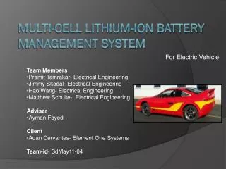
For Electric Vehicle. Team Members Pramit Tamrakar - EE Jimmy Skadal - EE Hao Wang - EE Matthew Schulte - EE William Zimmerman - EE Advisor Ayman Fayed Client Adan Cervantes- Element One Systems Team-id - SdMay11-04. Multi-Cell Lithium-Ion Battery Management System.

E N D
For Electric Vehicle • Team Members • PramitTamrakar - EE • Jimmy Skadal - EE • Hao Wang - EE • Matthew Schulte - EE • William Zimmerman - EE • Advisor • Ayman Fayed • Client • Adan Cervantes- Element One Systems • Team-id- SdMay11-04 Multi-Cell Lithium-Ion Battery Management System
Problem Statement Charging Goal • To develop an efficient and safe system for charging and monitoring of multi-cell series batteries in Electric Vehicles by using AC to DC converters. • 18 Series Batteries, 2.3 Ah each • 45 minute CCCV charge System Specifications CCCV Charging sequence for Lithium-Ion Batteries
Project Goals and System Diagram Full Scale System Diagram Design a Lithium Ion Battery Charger that is capable of safely charging 16 parallel packs of 90 cells in series (Large Scale System). Successfully build an 18 cell charger that is capable of monitoring and balancing the cells. (Small Scale System)
Project Plan • Acquire boards/parts from TI • Use built in capabilities to daisy chain the boards • Close the feedback loop • Connect the boost converter, buck converter, test board, current sensing resistor, amplifier, and aardvark software to ensure proper charging • Test & Prototype the small scales design • Hardware Cost • $2120.00
Project Design • BQ76PL536EVM-3 • Battery management system • Track the voltage and temp. for all batteries • MSP430 with buck circuit • GenerateAll necessary voltages and currents with PWM • Negative feed-back loop • Aardvark Interface • To display the status of the charging system Small Scaled System Diagram
Project Design Issue • Daisy-chained EVMs • Proved the ability to hook together multiple EVMs. • System Signal Components • Ordered MOSFET drivers and power resistor to operate our buck converter • Ordered components to amplify small signals produced by the micro-controller • SPI Communication • Programming MSP 430 in order to build SPI communication between micro-controller and EVMs
Buck Circuit Implementation and Testing • The buck circuit will take a voltage given by some supply and decrease the value as needed. • There will be a negative feedback loop in the system so the Buck can accurately output the desired current or voltage. Value of components for scaled down buck circuit Tested Buck Circuit with PSpice by changing the input PWM and observing the output.
Buck Testing • Variac wall transformer (rectified) to DC • Input DC from Variac at 65V • Buck output expectations: • 32.4V-64.6V • Max 3A • Power Resistor Test Load Buck Testing Schematic
EVM- Testing Plan • TI’s processor bq76PL536EVM-3 and Aardvark USB-SPI adaptor • Aardvark driver will be installed in a laptop before installing the TI evaluation software • Tested the EVM board with 12-26 VDC Power Supply • Plan to configure the EVM with cells • Use the TI’s WinGUI user interface software to monitor the status of the cell
EVM- Safety • The battery connections should be made secure, a loose connection may result in device destruction. • The ideal connection sequence is from pin P1.1 to pin 3.7 in order to avoid the any connection error • The Absolute Maximum voltage per IC is 36V • Caution must be taken when using the EVM as part of a stack , where lethal voltages may be present
MSP430 Programming • Code Composer Studio v4 • Tested modules: • High frequency clock • ADC • Timer/PWM • Basic feedback • Low Power Mode • Unfinished: • SPI communication