Download
1 / 26
340 likes | 686 Vues
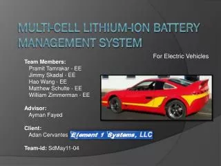
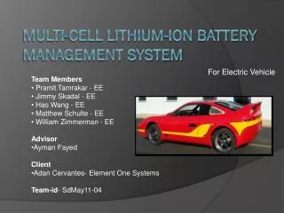
For Electric Vehicle. Team Members Pramit Tamrakar- Electrical Engineering Jimmy Skadal- Electrical Engineering Hao Wang- Electrical Engineering Matthew Schulte- Electrical Engineering Adviser Ayman Fayed Client Adan Cervantes- Element One Systems Team-id - SdMay11-04.

E N D
For Electric Vehicle • Team Members • Pramit Tamrakar- Electrical Engineering • Jimmy Skadal- Electrical Engineering • Hao Wang- Electrical Engineering • Matthew Schulte- Electrical Engineering • Adviser • Ayman Fayed • Client • Adan Cervantes- Element One Systems • Team-id- SdMay11-04 Multi-Cell Lithium-Ion Battery Management System
Problem Statement • Develop an efficient and safe system for charging and monitoring of multi-cell series batteries in Electric Vehicles using AC to DC Switching Power Converters.
Functional Requirement • Li-Ion Battery Management (90 cells in series) • Constant-Current Constant-Voltage (CCCV) charging procedure • Battery Gauging • Temperature Monitoring • Overcharge Protection • Achieve 100 miles range per charge
Non-Functional Requirements • Generating a 324 VDC power bus from a 120V VAC outlet • Ensuring safety
Constraints and Technology considerations • Constraints: The charging process • Technology: • Three Stages Charging Technology • Pre - charge Constant Current stage • Constant Current charging stage • Constant voltage charging stage • Voltage converter • Boost converter circuit • MSP430 Microcontroller • Constraints: High voltage control • Technology: • Scaling down by a factor about 4 (90 series cells to 24 series cells)
Market Survey • Commercially available switching mode power supply for electric vehicles is offered by Brusa. • The NLG5 provides a high voltage power source from a 120V or 240V wall outlet. • Cost: over $2,000 • Brusa does not have a Battery Management Systems. NLG503-light battery charger. 1.6 kW 200-540V, $2,145
Risk Mitigation • Testing and Simulation: To prevent component damage and ensure proper design, the system will be modeled to test for expected results. • Lower Volt System: With the 42V – 86.4V scaled down system, the risk a shock is reduced. • Smart and Safe: By knowing how to be safe and building the system with human/component safety in mind will aid in avoiding risk. Electric Shock: The risk of electric shock is possible when working with a charging system. System Component Damage: As power is being applied and the charging system is running, the risk of overheating, voltage/current spikes, and incorrect connections are possible.
Cost Breakdown Total: $520 Total: $2120.00
UCC28019AEVM Boost Circuit Will supply the needed maximum 324 volts to the buck circuit for the large scale charger 350 W Power Factor Correction (PFC) boost converter 390 VDC regulated output 0.9 A of load current Advanced fault protection
Buck circuit and Feedback Loop • The buck circuit will take the voltage generated by the boost buck down to cells • The negative feedback loop • Negative feedback tends to compare actual voltage with desired voltage and seeks to reduce the difference Scaled down buck circuit Value of components
Battery Management System • Will use TI’s processor bq76PL536EVM-3 and Aardvark USB-SPI adaptor • EVM-3 will monitor, balance and charge 24 cells in series • Will use Aardvark to gather the packet of information and display in the PC using using Evaluation software
Software Technology Platform • Use Ti’s Evaluation software to monitor the status of batteries
Test Plan • Subsystem test: • Boost Converter • System DC supply • Buck Converter with MSP430 Launch Pad • All necessary voltages and currents with PWM • Battery Management System communication • USB-SPI Processing GUI (PC) • Ability to control feedback loop from MSP430 to buck • Integration Test (scaled down): • 24 cell charge/discharge • 48V-86.4V CC (up to 3A), 86.4V CV until 0.3A
Prototype Implementations & Results • Coding for the MSP430 PWM output and ADC has been completed • Basic resistor divider input has been implemented to changed the PWM duty cycle • Components for the buck converter have been sourced
Task Distribution • System Design • Buck Converter-Matt, Hao • Boost Converter-Matt, Jimmy • Battery Management System-Pramit, Matt Jimmy, Hao
Plan for Next Semester • Obtain parts and evaluation module from TI • Use what we can to quickly expand the scaled down version. • Series PCB • Use single evaluation module • Implement the buck converter. • Implement communication between the evaluation module and the MSP430 • Display charging information with a pc