Download
1 / 129
3.17k likes | 5.72k Vues
INDUSTRIAL ROBOTICS U7MEA38. Prepared by Mr.SurryaPrakash.D Assistant Professor, Mechanical Department VelTech Dr.RR & Dr.SR Technical University. UNIT I INTRODUCTION.

E N D
INDUSTRIAL ROBOTICSU7MEA38 Prepared by Mr.SurryaPrakash.D Assistant Professor, Mechanical Department VelTech Dr.RR & Dr.SR Technical University
UNIT I INTRODUCTION • Definition of a Robot - Basic Concepts - Robot configurations - Types of Robot drives - Basic robot motions -Point to point control - Continuous path control.
Definition of a Robot • A machine that looks and acts like a human being. • An efficient but insensitive person • An automatic apparatus. • Something guided by automatic controls. E.g. remote control • A computer whose main function is to produce motion.
Law’s of Robotics Asimov proposed three “Laws of Robotics” • Law 1: A robot may not injure a human being or through inaction, allow a human being to come to harm • Law 2: A robot must obey orders given to it by human beings, except where such orders would conflict with a higher order law • Law 3: A robot must protect its own existence as long as such protection does not conflict with a higher order law
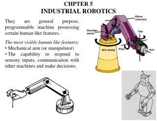
Robot anatomy • Robot manipulator consists of two sections: • Body-and-arm – for positioning of objects in the robot's work volume • Wrist assembly – for orientation of objects
Wrist • Wrist assembly is attached to end-of-arm • End effector is attached to wrist assembly • Function of wrist assembly is to orient end effector • Body-and-arm determines global position of end effector • Two or three degrees of freedom: • Roll • Pitch • Yaw
Robot configurations • Rectangular (or) Cartesian • Cylindrical (or) Post-type • Spherical (or) Polar • SCARA (Selective Compliance Assembly Robot Arm)
Cartesian/Rectangular Manipulator • straight, or linear motion along three axes: • in and out, (x) • back and forth (y) • up and down (z)
Cylindrical Manipulator • Rotation about the base or shoulder. (θ) • up and down (z) • in and out (R)
Polar or Spherical Manipulator • rotation about the base • Rotation about an axis in the vertical plane to raise and lower it. • reaches in and out.
SCARA Robot • Selective Compliance Assembly Robot Arm • the same work area as a cylindrical-coordinates robot. • the reach axis includes a rotational joint in a plane parallel to the floor.
Types of Robot drives Electric: All robots use electricity as the primary source of energy. • Electricity turns the pumps that provide hydraulic and pneumatic pressure. • It also powers the robot controller and all the electronic components and peripheral devices. • In all electric robots, the drive actuators, as well as the controller, are electrically powered. • Because electric robots do not require a hydraulic power unit, they conserve floor space and decrease factory noise. • No energy conversion is required.
Pneumatic: these are generally found in relatively low-cost manipulators with low load carrying capacity. • Pneumatic drives have been used for many years for powering simple stop-to-stop motions. • It is inherently light weight, particularly when operating pressures are moderate.
Hydraulic: are either linear position actuators or a rotary vane configuration. • Hydraulic actuators provide a large amount of power for a given actuator. • The high power-to-weight ratio makes the hydraulic actuator an attractive choice for moving moderate to high loads at reasonable speeds and moderate noise level. • Hydraulic motors usually provide a more efficient way of energy to achieve a better performance, but they are expensive and generally less accurate.
Basic Robot motions A robot manipulator can make four types of motion in travelling from one point to another in the workplace: • Slew motion : simplest type of motion. Robot is commanded to travel from one point to another at default speed. • Joint-interpolated motion: requires the robot controller to calculate the time it will take each joint to reach its destination at the commanded speed. • Straight-line interpolation motion: requires the end of the end effector to travel along a straight path determine in rectangular coordinates. • Useful in applications such as arc welding, inserting pins into holes, or laying material along a straight path. • Circular interpolation motion: requires the robot controller to define the points of a circle in the workplace based on a minimum of three specified positions. • Circular interpolation produces a linear approximation of the circle and is more readily available using a programming language rather than manual or teach pendant techniques.
Point to point control Point-To-Point: These robots are most common and can move from one specified point to another but cannot stop at arbitrary points not previously designated. • All Axes start and end simultaneously • All Geometry is computed for targets and relevant Joint changes which are then forced to be followed during program execution • Only the end points are programmed, the path used to connect the end points are computed by the controller • user can control velocity, and may permit linear or piece wise linear motion • Feedback control is used during motion to ascertain that individual joints have achieved desired location • Often used hydraulic drives, recent trend towards servomotors • loads up to 500lb and large reach Applications • pick and place type operations • palletizing • machine loading
Continuous path control Continuous Path: • It is an extension of the point-to-point method. this involves the utilization of more points and its path can be arc, a circle, or a straight line. • Because of the large number of points, the robot is capable of producing smooth movements that give the appearance of continuous or contour movement. • In addition to the control over the endpoints, the path taken by the end effector can be controlled • Path is controlled by manipulating the joints throughout the entire motion, via closed loop control. Applications • spray painting • polishing • grinding • arc welding
Controlled Path Controlled Path: It is a specialized control method that is a part of general category of a point-to-point robot but with more precise control. • The controlled path robot ensures that the robot will describe the right segment between two taught points. • Controlled-path is a calculated method and is desired when the manipulator must move in the perfect path motion.
UNIT II COMPONENTS & OPERATIONS • Basic control system concepts - control system analysis - robot actuation and fed back, Manipulators – direct and inverse kinematics, Coordinate transformation - Brief Robot dynamics. Types of Robot and effectors -Grippers - Tools as end effectors - Robot/End - effort interface.
Basic control system concepts • Open-Loop Control Systems • Closed-Loop Control Systems • Multivariable Control Systems
Open-Loop Control Systems • Open-Loop Control Systems utilize a controller or control actuator to obtain the desired response.
Closed-Loop Control Systems • Closed-Loop Control Systems utilizes feedback to compare the actual output to the desired output response
Manipulators • Manipulator consists of joints and links • Joints provide relative motion • Links are rigid members between joints • Various joint types: linear and rotary • Each joint provides a “degree-of-freedom” • Most robots possess five or six degrees-of-freedom
Degrees of freedom • Degree of Freedom is the number of independent relative motion in the form of translation and rotation • The body in space has got the maximum of 6 degrees of motion(3 translatory & 3 rotary motions) • Each Translatory has 1 DOF and each Rotary has 1 DOF
Kinematics • It is the branch of dynamics which deals with the relative motion existing between members.
Forward Kinematics (angles to position) • What you are given: • The length of each link • The angle of each joint • What you can find: • The position of any point (i.e. it’s (x, y, z) coordinates • Forward Kinematics of 2 link manipulator
Inverse Kinematics (position to angles) • What you are given: • The length of each link • The angle of each joint • What you can find: • The angles of each joint needed to obtain that position • Inverse kinematics of 2 link manipulator Squaring on both sides and adding
Types of Robot End effectors • Inflatable bladder • Two-finger clamp • Vaccum cups • Three-fingers clamp • Magnet head • Tubing pickup device
End-of-Arm-Tooling • This general class of devices is also called end-of-arm tooling (EOAT). • Robot end-of-arm tooling is not limited to various kinds of gripping devices. • Grippers not available by default in general-purpose robots • In some situations, a robot must change its gripper during its task. If so, the robot's wrist must be fitted with a quick-disconnect device.
Grippers • Grippers are end effectors used to grasp and manipulate objects. • Just like a hand, a gripper enables holding, tightening, handling and releasing of an object. • A gripper can be attached to a robot or it can be part of a fixed automation system
Gripper Actuation • Manual: Actuated by hand crank, wheel, levers, or other manual or mechanical means. • Electric: Grippers fingers or jaws actuated by electric motor, solenoid, etc. • Pneumatic: Gripper is actuated by compressed air acting on a cylinder or vanes. • Hydraulic: Gripper is actuated by hydraulic fluid acting on a cylinder or vanes.
Requirements for an effective gripper • Parts or items must be grasped and held without damage • Parts must be positioned firmly or rigidly while being operated on. • Hands or grippers must accommodate parts of differing sizes or even of varying sizes • Self-aligning jaws are required to ensure that the load stays centered in the jaws • Grippers or end effectors must not damage the part being handled. • Jaws or grippers must make contact at a minimum of two points to ensure that the part doesn’t rotate while being positioned.
UNIT III SENSING AND MACHINE VISION • Range sensing - Proximity sensing - Touch sensing - Force and Torque sensing. Introduction to Machine vision - Sensing and digitizing - Image processing and analysis.
Sensor • Sensor is a basic component of transducer. • The purpose of a sensor is to respond to some kind of an input physical property and to convert it into an electrical signal which is compatible with electronic circuits. • The sensor output signal may be in the form of voltage, current, or charge .
Sensor Types A. Based on power requirement: 1. Active: require external power, called excitation signal, for the operation 2. Passive: directly generate electrical signal in response to the external stimulus B. Based on sensor placement: 1. Contact sensors 2. Non-contact sensors
Why do Robots need sensors? • Provides “awareness” of surroundings • What’s ahead, around, “out there”? • Allows interaction with environment • Robot lawn mower can “see” cut grass • Protection & Self-Preservation • Safety, Damage Prevention, Stairwell sensor • Gives the robot capability to goal-seek • Find colorful objects, seek goals • Makes robots “interesting”
What can be sensed? • Light • Presence, color, intensity, content (mod), direction • Sound • Presence, frequency, intensity, content (mod), direction • Heat • Temperature, wavelength, magnitude, direction • Chemicals • Presence, concentration, identity, etc. • Object Proximity • Presence/absence, distance, bearing, color, etc. • Physical orientation/attitude/position • Magnitude, pitch, roll, yaw, coordinates, etc. • Magnetic & Electric Fields • Presence, magnitude, orientation, content (mod) • Resistance (electrical, indirectly via V/I) • Presence, magnitude, etc. • Capacitance (via excitation/oscillation) • Presence, magnitude, etc. • Inductance (via excitation/oscillation) • Presence, magnitude, etc.
Proximity sensor • Proximity sensors are devices that indicate when one object is close to another object. • The distances can be several millimeters and feet. • Widely used in general industrial automation • – Conveyor lines (counting, jam detection, etc) • – Machine tools (safety interlock, sequencing) • Usually digital (on/off) sensors detecting the presence or absence of an object
Force Sensor • The fundamental operating principles of force, acceleration, and torque instrumentation are closely allied to the piezoelectric and strain gage devices used to measure static and dynamic pressures. • Piezoelectric sensor produces a voltage when it is "squeezed" by a force that is proportional to the force applied. • Difference between these devices and static force detection devices such as strain gages is that the electrical signal generated by the crystal decays rapidly after the application of force. • The high impedance electrical signal generated by the piezoelectric crystal is converted to a low impedance signal suitable for such an instrument as a digital storage oscilloscope. • Depending on the application requirements, dynamic force can be measured as either compression, tensile, or torque force. • Applications may include the measurement of spring or sliding friction forces, chain tensions, clutch release forces.