IR beam pipe
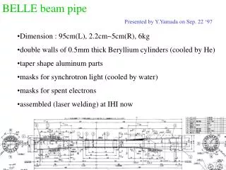
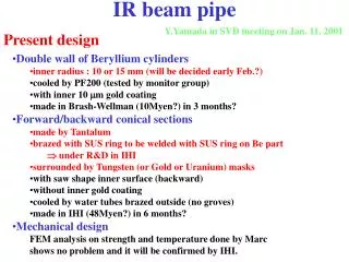
IR beam pipe. Y.Yamada in SVD meeting on Jan. 11, 2001. Present design. Double wall of Beryllium cylinders inner radius : 10 or 15 mm (will be decided early Feb.?) cooled by PF200 (tested by monitor group) with inner 10 m m gold coating made in Brash-Wellman (10Myen?) in 3 months?

IR beam pipe
E N D
Presentation Transcript
IR beam pipe Y.Yamada in SVD meeting on Jan. 11, 2001 Present design • Double wall of Beryllium cylinders • inner radius : 10 or 15 mm (will be decided early Feb.?) • cooled by PF200 (tested by monitor group) • with inner 10 mm gold coating • made in Brash-Wellman (10Myen?) in 3 months? • Forward/backward conical sections • made by Tantalum • brazed with SUS ring to be welded with SUS ring on Be part • under R&D in IHI • surrounded by Tungsten (or Gold or Uranium) masks • with saw shape inner surface (backward) • without inner gold coating • cooled by water tubes brazed outside (no groves) • made in IHI (48Myen?) in 6 months? • Mechanical design • FEM analysis on strength and temperature done by Marc • shows no problem and it will be confirmed by IHI.
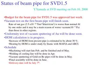
Background simulation • 1. Particle background (Karim) • Simulation only in straight section (dose(kRad/y) with design values) • SVD1 1st layer (R=3.0 cm) : (~100 krad/y measured) • 5.5(HER Brems.)+1.1(HER Coul.)+0.3(LER Brems.)+1.8(LER Coul.) • SVD2 1st layer (R=2.1 cm) with R=1.5 cm beam pipe : • 12.0(HER Brems.)+1.4(HER Coul.)+0.9(LER Brems.)+2.1(LER Coul.) • SVD2 1st layer (R=1.5 cm) with R=1 cm beam pipe : • 31.3(HER Brems.)+3.7?(HER Coul.)+2.3(LER Brems.)+8.1(LER Coul.) • Simulation of one turn in HER (without masks) • Brems. : no big change (straight section dominant) • Coulomb : increase by factor ~16 (equal contribution in any place of ring) • Vacuum bump study shows large contribution of straight section • need to simulate the effect of • (1) multi-turn, (2) movable masks and (3) offset of magnets • 2. Synchrotron light background (Sanjay) • QC1/QC2 are main sources, • but no serious problem found even in injection
Work shop in Hawaii on Jan. 26 and 26, 2001 • Jan. 25 • 1) Overview - 20 min. (Yamamoto) • 2) Vacuum pressure - 45 min. (Kanazawa) • 3) Configurations near IR - 15 min. (Kanazawa) • 4) Beam loss overview - 30 min. (Funakoshi) • 5) Aperture issues - 15 min. (Ohnishi) • 6) Orbit near IP - 15 min. (Ohnishi) • 7) Current and future beam parameters - 10 min. (Funakoshi) • 8) HOM heating - 30 min (Stanic) • 9) Synchrotron background simulation - 30 min (Swain) • 10) Particle background - 45 min (Trabelsi) • 11) Discussion • Jan 26 • 1) Monitoring - 30 min (Tsuboyama) • 2) Pressure bump studies - 45 min (Haba) • 3) Starball - 20 min (Yamamoto) • 4) SVD mechanical design - 30 min (Yamada) • 5) IR beampipe mechanical design overview - 30 min (Yamamoto) • 6) FEA analysis - 30 min (Rosen) • 7) Discussions