Download
1 / 39
400 likes | 436 Vues
This article discusses the potential applications and challenges of using piezoceramic sensors for detecting infrasound in various natural phenomena and atmospheric events. It introduces the Infrasound Pipe Array as a state-of-the-art wind noise sensor to replace large arrays, and highlights the characteristics of piezoceramic sensors such as resonant frequency, sensitivity, and temperature compensation. The high-frequency sensor is also explored for improved sound propagation experiments. The text delves into the comparison of different sensors and array deployments for effective monitoring and data collection.

E N D
Piezoceramic Sensors and Infrasound Technology Carrick L. Talmadge National Center for Physical Acoustics University of Mississippi, Oxford MS
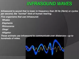
Potential Applications of Infrasound Sensors • monitoring potential atmospheric nuclear tests (CTBT applications) • natural hazard detection of volcanos, tornados, tsunamis • monitoring natural phenomena such as hurricanes and bolides • Atmospheric science applications such as studying structure of stratosphere, probing physics of the lower thermosphere.
Challenges of Atmospheric Infrasound • Noise associated with atmospheric turbulence (“wind noise”), especially at frequencies below 0.1 Hz. Conventionally this is solved by adding large “wind-noise filters” to sensors. The cost of the filters typically far exceeds the cost of the infrasound sensor itself. • Environmental exposure is a hazard to current, rather delicate microphones, so vaults are constructed to stablize temperature and protect the instrument from environmental exposure.
Infrasound Pipe Array: State of the Art Wind Noise Sensor
Goals of This Instrument Development • Replace large pipe arrays with array of infrasound sensors. • Ruggedize sensors, and construct them to be insensitive to thermal fluctuates: Removes requirement for instrument vault. • Make them low-cost enough ($750 vs $5000+) to make practicable multiple arrays of sensors. • Low replacement cost also reduces risk associated with damaged or destroyed sensors.
Piezoceramic Sensors • Resonant Frequency - 1.8 kHz (hinged condition) • Sensitivity - 3.4 mV/Pa • Temperature Compensation • Reverse bimorphs • Insulated enclosures, small openings • Charge Generating • Must operate into a high impendence
Frequency Response of Piezeoceramic Sensors higher frequencies strongly attenuated, phase becomes incoherent 3-dB cut-off for 35-mm element very flat amplitude/phase response below 500 Hz–ideal for long-distance sensing Band start frequency depends on design of preamplifier. We can reliably measure pressure signals down to periods of 105s.
Schematic of NCPA Sensors C50 pin-compatible connector This 4-element design reduces effects of temperature gradients across sensors. Current design has different base plate, sensor lid. Still Chaparral 50 compatible.
Characteristics of Sensor • • highly ruggedized • 0.0005 Hz- 100 Hz operating range (3-dB). Can be calibrated to 500-Hz. • plug compatible with Chaparral 50 • self-calibration using reciprocal calibration method has been demonstrated from 0.1–100 Hz, calibration chamber with calibrated volume source. • Sensor can be configured as accelerometer (or dual pressure/acceleration sensor with same sensing elements).
“High Frequency” Sensor • Allow use of microphone for low-frequency sound, long-range propagation experiments. • 0.1 Hz- 1000 Hz operating range, configurable gain • Improved vibrational isolation (elevated sensor applications). • More compact sensor packaging. • Vertical (4-m, 8-element) portable towers are in development at the NCPA.
2009 Nevada Field Deployment of Array Nominal array locations were at 180–250 km, in 10 km steps
Array Geometry • All infrasound microphones were NCPA sensors. • Outer sensors characteristics: 10 mHz–100 Hz, 0.13 V/Pa; center mike 1 mHz–100 Hz, 0.025V/Pa • Digitizers used were Geotech SMART 24 (“even” numbered array”) or Miltech Fence Posts (“odd numbered arrays”).
Sources for Nevada Deployment July 14, 2009 4 ton TNT-eq explosion 4, 20 and 80 tons-TNT equivalent explosions at the Utah Testing and Training Range (UTTR), as part of the Trident missile disposal program.
Source Capture–23 km South Source capture used 2 co-located microphones 23-km south of source. Assuming spherical spreading, source strength was about 70-Pa at 1 kilometer. Source capture used a Chaparral USB Digitizer.
Source Spectral Content “Scalloping” probably associated with multiple arrivals associated with propagation effects.
Average Noise Floor f–7/3 f–1 fc = 20 Hz (wind noise filter)
Seismic Signals Miltech Fence posts had 3-axis geophones (Geospace GS-32CT). Arrivals were observed on these sensors coincident with the infrasound sensors.
Frequency Spectrum Peak energy was near 0.7 Hz High-frequency tail above 20-Hz was unexpected. However, it was observed at all sites with two different recording systems, and with two different technologies (infrasound mikes, seismometer)
Conclusions • A new sensor technology incorporating piezoceramic sensors has been developed at the NCPA. • This technology was successfully field tested in a large scale deployment in Utah/Nevada from July 13–September 22, 2009. • Very few sensor related problems were encountered during experiment. • Main surprise was observation of high-frequency signals which are probably associated with nonlinear propagation effects at stratospheric elevations.