Affordable PC-Based Oscilloscope: A Student Engineering Project
This presentation outlines a student-led project to design a low-cost PC-based oscilloscope, aimed at providing fundamental oscilloscope functionalities for electronics enthusiasts and college students. The team, guided by Dr. David Carlson, focused on creating a self-contained device that interfaces with a PC via a nine-pin serial connector. Key objectives included developing companion software for live waveform displays and ensuring robust hardware design. The project highlights milestones in hardware and software development, PCB layout considerations, and future work opportunities to expand functionality.

Affordable PC-Based Oscilloscope: A Student Engineering Project
E N D
Presentation Transcript
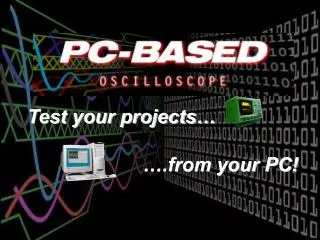
Test your projects… ….from your PC!
Today’s Presentation • Background • Problem Statement • Objectives • Milestones • Technical Approach • Future Work • Achievements; Conclusions • Questions
The PC Based Oscilloscope Team Students: Todd M. Buelow, EE Michael Jendrysik, CprE Chris Justice, EE Mike McClimans, EE Brian J. Smith, EE Advisor: Dr. David Carlson Associate Professor of Electrical & Computer Engineering
Background • High cost of Oscilloscopes makes them out of reach for many • Simple, low-cost oscilloscope are handy for small electronics projects • Useful to the typical college student and the electronic hobbyist
Problem Statement • To research, design, develop, and test a device that will take voltage vs. time measurements, as an oscilloscope does, and output those results to a PC • To present the digitized voltage measurements to the user in the form of a live waveform display via custom software
Objectives • Basic oscilloscope functionality • A self-contained module • Nine pin serial port connector to interface with a PC • BNC connections for scope probes • Control done via software
Milestones • Design hardware layout • Develop companion software • Develop microcontroller firmware • Fabricate PCB • Assemble circuit • Test and debug the module and software
PC Based Oscilloscope Basic Hardware Layout
Hardware Design Options • ISA Card • USB Port • Parallel Port • Serial Port
Hardware Design Options • Microcontroller ADC Simple, but slow • External ADC Faster, but more complex • Software selectable gain control Convenient, flexible, but considerable added complexity
Hardware Design Options • Static Gain Simple, but not as flexible • Single ended input Simple, no need for inverting supply, provides more precise ADC readings, but impractical for real use • Positive and negative input Flexible input signals, necessary for some applications requires inverting supply, less precise ADC readings potential noise
PCB Layout Considerations • PCB Design issues • Sensitive analog signals mixed with noisy digital circuitry • Small form-factor • Development board (ease of debug) • Donated board turn
PCB Layout Considerations • Good PCB layout implementation • Separate analog and digital circuitry • Path to isolated analog ground • Ground fill, ground plane • Power planes • Bypass, bypass, bypass • All surface mount components • 10 10 spacing rules • 4 layer board (Outer 2 layers are signal layers, inner two are power and ground planes)
Power supply External power supply (unregulated) CHA+ Probe hardware block diagram + PC-Based oscilloscope CHA- - Data bus Memory Analog to digital converter Instrumentation amplifiers Memory address Addresscounter CHB+ + Control CHB- - Digital Trigger Microcontroller Test output Serial to / from host PC Data Test signal generator Regulated power outputs Serial Translator 9 pin Connector CDJ 10/14/98
PC Based Oscilloscope Firmware • Goal: sampling, storing, & data communication with host PC • C or Assembly? • Assembly chosen due to • Tremendous amount of freeware example code • Free compilers/emulators • C compilers are all third party and little source code
PC Based Oscilloscope Firmware Three stages of development • First version • Check for commands from host and tell the host when messages received correctly • Set output pins to DC for 5 seconds after receiving a bad command • Send out square waves on output pins otherwise • Second Version • Basically a voltmeter • Samples every few seconds and sends to host • Third version • All the bells & whistles (full speed sampling, triggering, data buffering in memory)
PC Based Oscilloscope Firmware Store Data from ADCs Startup. Initialize Port & Data Is trigger condition met? No. Initialize Ports, Data Look for host PC No. Continue polling for PC command. Yes. PC command present? Go to next memory address. Store data. Yes. Analyze command. No. Keep filling. Is memory full? No. Prepare for trigger mode. Does PC demand streaming data? Yes. Send data in memory out to serial port. Yes. Prepare for continuous output. Select Channel, read data from ADC. No. Look for new command. Yes. Send more. Is there more data in the memory? Send data to serial port.
Host PC Software • Software Development • Visual C++ 6 • Microsoft Foundation Class (MFC) • Dialog based • Compatible with Microsoft Windows 95/98 • Software Features • Time/Voltage scaling • Individual channel control • Measurements, triggers • Adjustable ground • User friendly • Possessing the look and feel of real oscilloscope
Host PC Software • Software Operation • Win32 file handles for serial operation • No device driver needed • Trigger mode • Streaming mode • Receive data via serial port
Host PC Software Screenshot Save settings between testing sessions. Setup triggers for data collection. Modify the time scaling with ease. Change Voltage scaling at the push of a button. Add or subtract 2 waveforms. Take measurements and cut & paste the results to a lab report. Sample data at a regular basis, or only when you want it.
Future Work • Software • Firmware • Hardware • Additions: • More math functions (FFT, etc.) • Matlab and Excel datalinks in software • Marketing strategies
What We Learned • Working together • Communication among team members • Goal setting and co-motivation