Download
1 / 55
550 likes | 742 Vues
Introduction to Databases, Database Design and SQL Zornitsa Zaharieva CERN Accelerators and Beams Department Controls Group, Data Management Section /AB-CO-DM/ 08-SEP-2005. Contents. : Introduction to Databases : Main Database Concepts

E N D
Introduction to Databases, Database Design and SQL Zornitsa Zaharieva CERN Accelerators and Beams DepartmentControls Group, Data Management Section /AB-CO-DM/ 08-SEP-2005
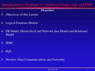
Contents : Introduction to Databases : Main Database Concepts : Conceptual Design - Entity-Relationship Model : Logical Design - Relational Model : Normalization and Denormalization : Introduction to SQL : Implementing the Relational Model through DDL : DML Statements – SELECT, INSERT, DELETE, UPDATE, MERGE : Transactions : Best Practices in Database Design
Introduction to Databases • Data stored in file systems – problems with : redundancy : maintenance : security : efficient access to the data • Database Management Systems Software tools that enable the management (definition, creation, maintenance and use) of large amounts of interrelated data stored in a computer accessible media.
Capabilities of a Database Management System • Manage persistent data • Access large amounts of data efficiently • Support for at least one data model • Support for certain high-level language that allow the user to define the structure of the data, access data, and manipulate data • Transaction management – the capability to provide correct, concurrent access to the database by many users at once • Access control – the ability to limit access to data by unauthorized users, and the ability to check the validity of data • Resiliency – the ability to recover from system failures without losing data
Data Model • A mathematical abstraction (formalism) through which the user can view the data • Has two parts 1. A notation for describing data 2. A set of operations used to manipulate that data • Examples of data models : relational model : network model : hierarchical model : object model
Conceptual Design Produces the initial model of the real world in a conceptual model Logical DesignConsists of transforming the conceptual schema into the data model supported by the DBMS Physical DesignAims at improving the performance of the final system Business Information Requirements Design Phases • Difficulties in designing the DB’s effectively brought design methodologies based on data models • Database development process Conceptual Data Modeling Logical Database Design Physical Database Design Operational Database
The process of constructing a modelof the information used in an enterprise Is a conceptual representation of the data structures Is independentof all physical considerations Should be simple enough to communicate with the end user Should be detailedenough to create the physical structure Conceptual Design Business information requirements Conceptual Design Conceptual model (Entity-Relationship Model)
Naming db Zornitsa Zaharieva – CERN /AB-CO-DM/ Information Requirements – CERN Controls Example “There is a need to keep an index of all the controls entities and their parameters coming from different controls systems. Each controls entity has a name, description and location. For every entity there might be several parameters that are characterized by their name, description, unit, quantity code, data type and system they are sent from. This database will be accessed and exchange data with some of the existing databases related to the accelerators controls. It will ensure that every parameter name is unique among all existing controls systems.” A1 additional slides
Hierarchical model Network model Relational model Entity-Relationship Model • The Entity-Relationship model (ER) is the most common conceptual model for database design nowadays • No attention to efficiency or physical database design • Describes data as entities,attributes, and relationships • It is assumed that the Entity-Relationship diagram will be turned into one of the other available models during the logical design Entity-relationship model
Entity • A thing of significance about which the business needs to store information • trivial example: employee, department CERN controls example: controls_entity, location, entity_parameter, system, quantity_code, data_type • Entity instance – an individual occurrence of a given entity • trivial example: a single employee CERN controls example: a given system (e.g. SPS Vacuum) Note:Be careful when establishing the ‘boundaries’ for the entity, e.g.entity employee – all employees in the company or all employees in a given department – depends on the requirements “a thing that exists and is distinguishable” J. Ullman Remote Database /edmsdb/ Local Database /cerndb1/
Attributes • Attributes are properties which describe the entity • attributes of system - id, description, comments • Attributes associate with each instance of an entity a value from a domain of values for that attribute • set of integers, real numbers, character strings • Attributes can be • : optional • : mandatory • A key- an attribute or a set of attributes, whose values uniquely identify each instance of a given entity SYSTEM # id * description o comments
ENTITY_PARAMETER # id* description o expert_name …… SYSTEM # id* description produces is generated by Relationships • Associations between entities • examples: employees are assigned to departments entity_parameters are generated by systems • Degree - number of entities associated with a relationship (most common case - binary) • Cardinality - indicates the maximum possible number of entity occurrences • Existence - indicates the minimum number of entity occurrences set of integers, real numbers, character strings : mandatory : optional
Relationship Cardinality • One-to-One (1:1)one manager is a head of one department • Note:Usually this is an assumption about the real world that the database designer could choose to make or not to. • One-to-Many (1:N)one system could generate many parameters one parameter is generated by only one system • Many-to-Many (N:M)many employees are assigned to one project one employee is assigned to many projects
CERN Controls Example • Entity-Relationship diagram example – LHC Naming Database
Business Information Requirements Conceptual Data Modeling Logical Database Design Physical Database Design Operational Database Logical Design • Translate the conceptual representation into the logical data model supported by the DBMS Logical Database Design Conceptual model(Entity-Relationship Model) Logical Design Normalized Relational Model
Relational Model • The most popular model for database implementation nowadays • Supports powerful, yet simple and declarative languages with which operations on data are expressed • Value-oriented model • Represents data in the form of relations • Data structures – relational tables • Data integrity – tables have to satisfy integrity constraints • Relational database – a collection of relations or two-dimensional tables
Relational Table • Composed by named columns and unnamed rows • The rows represent occurrences of the entity • Every table has a unique name • Columns within a table have unique names • Order of columns is irrelevant • Every row is unique • Order of rows is irrelevant • Every field value is atomic (contains a single value)
Primary Key (PK) and Foreign Key (FK) • Primary Key - a column or a set of columns that uniquely identify each row in a table • Composite (compound) key • Role is to enforce integrity- every table must have a primary key • For every row the PK : must have a non-null value : the value must be unique : the value must not change or become ‘null’ during the table lifetime : columns with the above mentioned characteristics are candidate keys • Foreign Key - column(s) in a table that serves as a PK of another table • Enforces referential integrity by completing an association between two tables
Data Integrity • Refers to the accuracy and consistency of the data by applying integrity constraint rules Constraint type Explanation _________________________________________________________________________ _ Entity Integrity No part of a PK can be NULL----------------------------------------------------------------------------------------------------------------Referential Integrity A FK must match an existing PK value or else be NULL---------------------------------------------------------------------------------------------------------------- Column Integrity A column must contain only values consistent with the defined data format of the column ----------------------------------------------------------------------------------------------------------------User-defined Integrity The data stored in the database must comply with the business rules
From Entity-Relationship Model to Relational Model Entity-Relationship model Entity Attribute Key Relationship • Relational model • Relational table • Column (attribute) • Primary Key (candidate keys) • Foreign Key SYSTEM # id * description
Relationships Transformations • Binary 1:1 relationshipsSolution : introduce a foreign key in the table on the optional side • Binary 1:N relationship • Solution : introduce a foreign key in the table on the ‘many’ side • M:N relationshipsSolution : create a new table; : introduce as a composite Primary Key of the new table, the set of PKs of the original two tables
CERN Controls Example • Relational Model diagram example – before normalization
Normalization • A series of steps followed to obtain a database design that allows for consistent storage and avoiding duplication of data • A process of decomposing relationships with ‘anomalies’ • The normalization process passes through fulfilling different Normal Forms • A table is said to be in a certain normal form if it satisfies certain constraints • Originally Dr. Codd defined 3 Normal Forms, later on several more were added • For most practical purposes databases are considered normalized if they adhere to 3rd Normal Form Relational db model 1st Normal Form 2nd Normal Form 3rd Normal Form Boyce/Codd Normal Form 4th Normal Form 5th Normal Form Normalized relational db model
Denormalization • Queries against a fully normalized database often perform poorly • Explanation:Current RDBMSs implement the relational model poorly. A true relational DBMS would allow for a fully normalized database at the logical level, whilst providing physical storage of data that is tuned for high performance. • Two approaches are used • Approach 1:Keep the logical design normalized, but allow the DBMS to store additional redundant information on disk to optimize query response (indexes, materialized views, etc.). In this case it is the DBMS software's responsibility to ensure that any redundant copies are kept consistent. • Approach 2:Use denormalization to improve performance,at the cost of reduced consistency
Denormalization • Denormalization is the process of attempting to optimize the performance of a database by adding redundant data • This may achieve (may not!) an improvement in query response, but at a cost • There should be a new set of constraints added that specify how the redundant copies of information must be kept synchronized • Denormalization can be hazardous : increase in logical complexity of the database design : complexity of the additional constraints • It is the database designer's responsibility to ensure that the denormalized database does not become inconsistent
CERN Controls Example • Relational Model diagram example – after normalization
Structured Query Language • Most commonly implemented relational query language • SQL : originally developed by IBM : official ANSI standard • Used to create, manipulate and maintain a relational database by using • Data Definition Language (DDL) : defines the database schema by creating, replacing, altering and dropping objects – e.g. CREATE, DROP, ALTER, RENAME, TRUNCATE table • Data Manipulation Language (DML) : manipulates the data in the tables by inserting, updating, deleting and querying data – e.g. SELECT, INSERT, UPDATE, DELETE • Data Control Language (DCL) : controls access to the database schema and its objects – e.g. GRANT, REVOKE privileges : guarantees database consistency and integrity
Database Schema Implementation • Definition:Database schema is a collection of logical structures of data • The implementation of the database schema is realized through the DDL part of SQL • Although there is a standard for SQL, there might be some features when writing the SQL scripts that are vendor specific • Some commercially available RDBMS : Oracle : DB2 – IBM : Microsoft SQL Server : Microsoft Access : mySQL
Create Table • Each attribute of a relation (column in a table) in a RDBMS has a datatype that defines the domain of values this attribute can have • The datatype for each column has to be specified when creating a table : ANSI standard : Oracle specific implementation • Create table - describes the layout of the table by providing : table name : column names • : datatype for each column • : integrity constraints – PK, FK, column constraints, default values, not null • CREATE TABLE systems ( • sys_id VARCHAR2(20) ,sys_description VARCHAR2(100) );
Constraints • Primary Key • ALTER TABLE systems ADD (CONSTRAINT SYSTEM_PK PRIMARY KEY (sys_id)); • Foreign Key • ALTER TABLE entity_parameters ADD (CONSTRAINT EP_SYS_FK FOREIGN KEY (system_id) REFERENCES systems(sys_id)) • Unique Key • ALTER TABLE entity_parameters ADD (CONSTRAINT EP_UNQ UNIQUE (ep_name));
Sequences • A db object that generates in in/de-creasing order a unique integer number • Can be used as PK for a table(in the absence of a more ‘natural’ choice) • Better than generating ID in application code : very efficient thanks to caching : uniqueness over multiple sessions, transaction safe • Get sequence values : current value : next value CREATE SEQUENCE ep_seqSTART WITH 1 NOMAXVALUENOMINVALUENOCYCLENOCACHE SELECT ep_seq.NEXTVAL FROM DUAL; SELECT ep_seq.CURRVAL FROM DUAL;
Basic DML Statements - SELECT • Retrieve all available data in a table • Retrieve a sub-set of the available columnstreating NULL values and set the order of the rows in the result set • Retrieve all distinct values in a column • Assign pseudonyms to the columns to retrieve and concatenating column values • Data can be grouped and summary values computed SELECT * FROM employees; SELECT name ,NVL(email, ‘-’) FROM employees ORDER BY name ASC; SELECT DISTINCT div_id FROM employees; SELECT first_name || name AS employee_name FROM employees; SELECT customer_id, COUNT(*) AS orders_per_customer FROM orders GROUP BY customer_id;
Set Operators – Combining Multiple Queries • SELECT name FROM visitors UNION • SELECT name FROM employees; • Union without duplicates (1+2) • Union with duplicates (1+2+3) • Intersect (3) • Minus (1) • SELECT name FROM visitors UNION ALL • SELECT name FROM employees; • SELECT name FROM visitors INTERSECT • SELECT name FROM employees; • SELECT name FROM visitors MINUS • SELECT name FROM employees; 3 2 1
Restricting the Data Selection • Need to restrict and filter the rows of data that are displayed • Clauses and Operators • : WHERE • : comparisons operators (=, >, < …..) • : BETWEEN, IN • : LIKE • : logical operators (AND,OR,NOT) SELECT * FROM employees WHERE emp_id = 30; SELECT name FROM employees WHERE salary > 10000; SELECT COUNT(*) FROM employees WHERE salary BETWEEN 1000 AND 2000; SELECT div_name FROM divisions WHERE div_id IN ( SELECT div_id FROM employees WHERE salary > 2000); SELECT * FROM employees WHERE name LIKE ‘C%’; • SELECT * FROM employees WHERE div_id = 20 • AND hiredate > TO_DATE(‘01-01-2000', ‘DD-MM-YYYY');
NATURAL Join • Relates rows of two different tables sharing common values in one or more columns of each table • Typical case: a foreign key referring to a primary key • What are the names of the employees and their departments? SELECT e.ename ,d.dname FROM emp e ,dept d WHERE e.deptno = d.deptno;
Subqueries • Logically, think of sub-queries in the following way: • Sub-queries (inner queries) execute once before the main query • The sub-query results are used by the main query (outer query) Who works in the same department as Clark? SELECT ename FROM emp WHERE deptno = (SELECT deptno FROM emp WHERE ename = 'CLARK');
Correlated Sub-queries • In previous sub-queries the inner query was executed only once before the main query and the same inner query result applies to all outer query rows • The inner query is evaluated for each row produced by the outer query • Who are the employees that receive more than the average salary of their department? SELECT empno, ename, sal, deptno FROM emp e WHERE sal > (SELECT AVG(sal) FROM emp WHERE deptno = e.deptno) ORDER BY deptno, sal DESC;
Inline views – Sub-queries in the FROM clause • What are the employees salaries and the maximum salary in their department? • SQL> SELECT ename, sal, MAX(sal), deptno FROM emp; • SELECT ename, sal, MAX(sal), deptno FROM emp • * • ERROR at line 1: • ORA-00937: not a single-group group function • We can use a “inline view” as the data source on which the main query is executed (FROM clause) SELECT e.ename ,e.sal ,a.maxsal ,a.deptno FROM emp e, (SELECT max(sal) maxsal ,deptno FROM emp GROUP BY deptno) a WHERE e.deptno = a.deptno ORDER BY e.deptno ,e.sal DESC;
DELETE FROM employees; DELETE FROM employees WHERE div_id = 3; DELETE FROM employees WHERE name = UPPER(‘smith’); Basic DML Statements – Insert and Delete • Insert data in a table • Delete data INSERT ALL WHEN ottl < 100000 THEN INTO small_orders VALUES(oid, ottl, sid, cid) WHEN ottl > 100000 and ottl < 200000 THEN INTO medium_orders VALUES(oid, ottl, sid, cid) WHEN ottl > 200000 THEN INTO large_orders VALUES(oid, ottl, sid, cid) WHEN ottl > 290000 THEN INTO special_orders SELECT o.order_id oid ,o.customer_id cid ,o.order_total ottl ,o.sales_rep_id sid ,c.credit_limit cl , c.cust_email cem FROM orders o ,customers c WHERE o.customer_id = c.customer_id; INSERT INTO employees ( emp_id ,div_id ,name ,hire_date ) VALUES ( emp_seq.NEXTVAL ,3 ,UPPER(‘Smith’) ,SYSDATE ); INSERT INTO bonuses SELECT employee_id ,salary*1.1 FROM employees WHERE commission_pct > 0.25 * salary;
UPDATE employees SET salary = 1000 ; UPDATE employees SET salary = salary+1000; UPDATE employees SET salary = 1000 WHERE name=‘SMITH’; UPDATE employees SET salary = salary+1000 WHERE div_id = 3; Basic DML Statements – Update and Merge • Update data • Merge data MERGE INTO bonuses B USING (SELECT employee_id ,salary ,department_id FROM employees WHERE department_id = 80) S ON (B.employee_id = S.employee_id) WHEN MATCHED THEN UPDATE SET B.bonus = B.bonus + S.salary*.01 WHEN NOT MATCHED THEN INSERT (B.employee_id, B.bonus) VALUES (S.employee_id, S.salary*0.1);
Transaction is a sequence of SQL statements that Oracle treats as a single unit. Transaction can start with SET TRANSACTION : READ COMMITTED mode – other DML statements (users) will wait until the end of the transaction, if they try to change locked rows : SERIALIZABLE mode – other DML statements (users) will get error if they try to change locked rows Transaction ends with COMMIT or ROLLBACK statement.: the set of changes is made permanent with the COMMITstatement : part or all transactions can be undone with the ROLLBACKstatement : SAVEPOINT is a point within a transaction to which you may rollback : Oracle implicitly commits the current transaction before or after a DDL statement Transactions What happens if the database crashes in the middle of several updates?
Best Practices in Database Design • ‘Black box’ syndrome : understand the features of the database and use them • Relational database or a data ‘dump’ : let the database enforce integrity : using the power of the relational database – manage integrity in multi-user environment : using PK and FK : not only one application will access the database • : implementing constraints in the database, not in the client or in the middle tier, is faster • : using the right datatypes
Best Practices in Database Design • Not using generic database models : tables - objects, attributes, object_attributes, links : performance problem! • Designing to perform • Creating a development (test) environment • Testing with real data and under real conditions
Development Tools • Oracle provided tools : Oracle Designer • : SQL* Plus • : JDeveloper • Benthic Software - http://www.benthicsoftware.com/ • : Golden • : PL/Edit • : GoldView • : at CERN - G:\Applications\Benthic\Benthic_license_CERN.html • Microsoft Visio • CAST - http://www.castsoftware.com/ • : SQL Code-Builder
References [1] Ensor, D., Stevenson, I., Oracle Design, O’Reilly, 1997 [2] Kyte, T., Effective Oracle by Design, McGraw-Hill, [3] Loney, K., Koch, G., Oracle 9i – The Complete Reference, McGraw-Hill, 2002 [4] Oracle course guide, Data Modeling and Relational Database Design, Oracle, 1996 [5] Rothwell, D., Databases: An Introduction, McGraw-Hill, 1993 [6] Ullman, J., Principles of Databases and Knowledge-Base Systemsvolumn 1, Computer Science Press, 1988 [7] Oracle on-line documentation http://oracle-documentation.web.cern.ch/oracle-documentation/
End; Thank you for your attention! Zornitsa.Zaharieva@cern.ch
Naming db Zornitsa Zaharieva – CERN /AB-CO-DM/ Information Requirements – CERN Controls Example “There is a need to keep an index of all the controls entities and their parameters coming from different controls systems. Each controls entity has a name, description and location. For every entity there might be several parameters that are characterized by their name, description, unit, quantity code, data type and system they are sent from. This database will be accessed and exchange data with some of the existing databases related to the accelerators controls. It will ensure that every parameter name is unique among all existing controls systems.” A1 additional slides
Information Requirements – CERN Controls Example Samples of the data that has to be stored: controls_entity name: VPIA.10020 description: Vacuum Pump Sputter Ion type A in location 10020 entity_code: VPIA expert_name: VPIA_10020 accelerator: SPS location_name: 10020 location_class: SPS_RING_POS location_class_description: SPS Ring position entity_parameter name: VPIA.10020:PRESSURE description: Pressure of Vacuum Pump Sputter Ion type A in location 10020 expert_name: VPIA.10020.PR unit_id: mb unit_description: millibar data_type: NUMERIC quantity_code: PRESSURE system_name: SPS_VACUUM system_description: SPS Vacuum A2 additional slides
ENTITY Soft box Singular name Unique Uppercase ER Modeling Conventions • If you use Oracle Designer the following convention is used: • attribute • Singular name • Unique within the entity • Lowercase • Mandatory (*) • Optional (o) • Unique identifier (#) ENTITY_PARAMETER # id * description o expert_name* unit_id* unit_description example Note:There are different conventions for representing the ER model! A3 additional slides