Download
1 / 21
220 likes | 268 Vues
Explore innovative film-like X-ray detectors based on Lithium Fluoride for high spatial resolution and versatile imaging applications in biology and material science.

E N D
Lithium Fluoride Thin Film Detectors for Soft X-Ray Imaging at High Spatial Resolution R.M. Montereali1, S. Almaviva1, F. Bonfigli1, A. Cricenti2, A. Faenov3, F. Flora1, P. Gaudio4, A. Lai1, S. Martellucci4, E. Nichelatti5, T. Pikuz3 , L. Reale6, M. Richetta4, M.A. Vincenti1 http://www.frascati.enea.it/fis/lac/solidstate/ montereali@frascati.enea.it 1ENEA, C.R. Frascati, Via E. Fermi 45, 00044 Frascati (Rome) Italy 2CNR, Istituto di Struttura della Materia, Via Fosso del Cavaliere 100, 00133 Rome, Italy 3Kansai Photon Science Institute, Kizu-gawa, Japan and Joint Institute for High Temperatures and Russian Academy of Sciences, Moscow, 125412, Russia 4University Tor Vergata, V. del Politecnico 1, 00133 Rome, Italy 5ENEA, C.R. Casaccia, V. Anguillarese 301, 00123 S. Maria di Galeria (Rome) Italy 6University of L’Aquila and INFN, Dip. di Fisica, Coppito, L’Aquila, Italy
Introduction and motivation We recently proposed (ENEA patent, n° TO2002A000575,N. WO2004/005906) innovative film-like soft X-ray imaging detectorsbased on photoluminescence (PL) of radiation-inducedactive color centersinLithium Fluoride (LiF) thin layers, with High spatial resolution Large field of view Wide dynamic range Efficient photoluminescence readout process Easy handling: no development needs and no sensitivity to visible light Versatility: compatible with permanent protective layers and different substrates They are currently under further development for imaging applications inbiology, photonics, material science, device developments, characterization of intense X-ray sources… • Introduction Lithium Fluoride: material properties Primary and aggregate electronic defects in LiF • Experimental • LiF based X-ray detectors: principle of operation and peculiarities • LiF films: growth and characterization X-ray irradiation and characterization of LiF crystals and films • X-ray imaging results Photonics: direct transfer of sub-micrometric luminescent patterns Contact X-ray microscopy, even for in vivo biological samples • Conclusions and future perspectives Outline
Lithium Fluoride (LiF) Color Centers (CCs): point defects in insulating materials Alkali Halides (AH): ionic crystals with fcc structure, optically transparent from near UV to IR. LiF stands apart because it is almost non-hygroscopic; it can hostCCs stable at RT; it can hostlaser active CCs tunable in a broad wavelength range in the visible and near IR. polycrystalline LiF films can be grown by thermal evaporation on different substrates; LiF can be colored only by ionizing radiation, like elementary particles and ions, as well as photons, such us EUV light, X-rays, rays and even intense ultra-short (fs) laser pulses. Irradiation of LiF gives rise to stable formation of primary and aggregate CCs, which generally coexist with often overlapping absorption bands.
Laser active color centers in LiF at RT F centeris an anion vacancy occupied by an electron; it is not an optically active centers in LiF. F2and F3+centers are laser active F-aggregate defects, consisting in two electrons bound to two and three close anion vacancies, respectively.
LiF films grown by thermal evaporation Ts (a) (b) oscillating quartz substrate holder t crucible (c) (d) Deposition parameters: Pressure< 10-6 mbar Evaporation rate R= 0.5-2 nm/s Film thickness tup to 6 m Substrate temperature Ts=30-350°C Nature of the substrate LiF films of different thicknesses t grown at different substrate temperature Ts (a) t 1 m, Ts=30°C (b) t 1 m, Ts=300°C (c) t 1.75 m, Ts=30°C (d) t 1.75 m, Ts=300°C on glass substrates R.M.Montereali et al., Thin Solid Films 196(1991)75
Peculiarities of EUV and soft X-rays irradiation of LiF 6 m) m 5 LiF ( 4 3 Attenuation length in 2 1 0 0 200 400 600 800 1000 1200 1400 1600 1800 2000 Photon energy ( eV) nm) 100 80 60 40 Attenuation length ( 20 0 0 20 40 60 80 100 120 Photon energy ( eV) - See smaller features X-ray microscopy - Write smaller patterns EUV Lithography EUV SXR EUV: 20 < h < 300 eV SXR: 0.3 < h < 3 keV WW : 4.4 - 2.3 nm (0.28 - 0.53 keV) Lower scattering cross-section: it limits lateral spreading of the beam. Neutrality: it avoids surface charge effects in insulating materials. Low penetration depth, dependent from the selected energy. EUVL =13.5 nm
LiF-based X-ray detector: writing and reading techniques Photoluminescence of F2, F3+ CCs (535-670 nm) Pumping ligth (458-488 nm) Irradiated LiF detector Writing process: contact mode Readout process: Optically Stimulated Luminescence (OSL) X-RAY LiF detector Irradiated LiF detector The photoluminescent patterns, stored in the irradiated LiF samples, are observed by using optical microscopes in fluorescence mode.Irradiation with blue light excites the visible photoluminescence of the F2 and F3+ defects locally created in the areas previously exposed to the X-ray beam. Permanent fluorescent patterns based on F2andF3+defects in LiFcan be produced by using several X-ray sources in different configurations (contact mode, direct writing, projection mode, etc.)
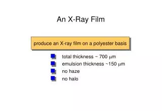
Imaging detectors for X-ray microscopy and radiography Photographic film (Kodak DEF) Grain size 1.5 mm Fluence dynamic range: 1 nJ/cm2 – 0.1 mJ/cm2 Readout: development + optical reading (absorption) Drawback: no visible light exposure Photoresist PMMA Molecule size 0.01 mm Fluence dynamic range: 1 mJ/cm2 – 50 mJ/cm2 Readout: development + AFM Image Plate, IPs (Fuji HR-S) Grain size 5 mm Fluence dynamic range: 1 pJ/cm2 – 0.1 mJ/cm2, linear response Readout: optical reading (OSL) Drawback: fading LiF detector Defect size 0.001 mm Fluence dynamic range: 0.1 mJ/cm2 – 1 J/cm2 (under investigation) Readout system: optical reading (PL)
X-ray imaging experiments SNOM collection mode - (CNR-ISM) Confocal Laser Scanning Microscope – SSL Lab ENEA Energy range:EUV, soft X-rays, hard X-rays, from 20 eV to 10 keV X-ray sources:laser plasma, synchrotrons, X-ray lasers, X-ray tubes Imaging detectors:LiF crystals LiF films Samples:biological samples (in vivo cells, insect wings, pollens, leafs, human hairs, etc.) micro-nanostructures (metallic masks, Phase Fresnel Zone Plate PFZP, etc.) Irradiation technique:lensless imaging,contact mode in absorption contrast Optical reading process:fluorescence microscopy Confocal Light Scanning Microscope, CLSM Scanning Near Field Microscope, SNOM Nikon Eclipse 80i equipped with a c.w. Argon laser (lexc = 458 nm). The confocal system allows to reach a higher lateral resolution respect to conventional fluorescence microscopes (resolution is increased up to 30%).
Micro-radiography of a dragonfly (Pyrrhesoma nymphula) wing 2 mm Wing micro-radiography on a 2 m thick LiF film at optical microscope obtained by observing the photoluminescence (PL), under the laser pumping wavelength of 458 nm. (S.Bollanti et al, Nuovo Cimento 20D (1998) 1685) http://www.frascati.enea.it/fis/lac/excimer/index-exc.html Biological sample: dragonfly (Pyrrhesoma nymphula) wing Detector: 2 mm thick LiF film evaporated on glass, Exposure: LPP at Excimer Lab, ENEA C.R. Frascati, Rotating metallic target: copper, tantalum, iron, etc, l= 60 – 0.6 nm, h = 2 keV - 20 eV, Emax = 250 eV Sample-Source distance: 5 – 15 cm on the normal Tight laser focusing, point-like source behaviour Radiation dose uniform on a large area, up to (4x4)cm2, W ~ 0.15 mJ/cm2/shot, P~3GW/cm3/shot G.Baldacchini, F.Bonfigli, A.Faenov, F.Flora, R.M.Montereali, A.Pace, T.Pikuz, L.Reale, J. Nanoscience and Nanotechnology 3,6(2003)483
Luminescent regular patterns based on CCs in LiF 3 mm 60 m Arrays of miniaturized light sources Copper mesh 2000 lpi, array of luminescent patterns with 12.5 m period. Copper mesh 400 lpi LiF crystal Target:Ta G. Baldacchini, F. Bonfigli, F. Flora, R.M. Montereali, D. Murra, E. Nichelatti, A. Faenov, T. Pikuz, Appl. Phys. Lett. 80, 4810 (2002)
Photoluminescent nano-structures on LiF crystals and films Resolution test: mask with patterns of submicrometric decreasing pitch from 1.6 μm a 0.4 μm (nanofabbrication through EBL on Si3N4 membrane and Au galvanic growth, CNR-IFN, Rome). Polipropilene (1 μm) Au (100 nm) Si3N4 (100 nm) Si (300 μm) Spatial resolution limit of contact lithography by LPP source Penumbra blurring effect ~ 0.1 nm 800 nm 400 nm Diffraction blurring effect ~ 36 nm F: diameter of the X-ray source (~ 100 mm) G: gap between mask and sample (~ 10 mm) d: distance between sample and X-ray source (~ 10 cm), : wavelength of incident radiation (~ 13 nm) Confocal images of X-ray micro-radiography of gold fringes mask on a LiF film on Si <100> substrate, t = 650 nm. 200 nm 400 nm Overlapping of the gold fringes
LiF based detectors: higher spatial resolution 2 1 Scanning Near Field Microscope (SNOM) observation Profile 1 Regular luminescent pattern on LiF film (Si substrate, t = 214 nm) 150 nm Profile 2 75 nm optical image topographic image 30 x 40 um2 SNOM image of a mosquito wing micro-radiograph stored in a LiF film. Edge resolution of 50 nm, corresponding to l/12. 50 nm A.Ustione, A.Cricenti, F.Bonfigli, F.Flora, A.Lai, T.Marolo, R.M. Montereali, G. Baldacchini, A. Faenov, T. Pikuz, L. Reale, Appl. Phys. Lett. 88 (2006)
In vivo soft X-ray microscopy of Chlorella cells Soft X-Ray Microscopy(l> 1 nm , E < 1 keV) was introduced for imaging of internal structure of biological samples in their normal living state, at a high spatial resolution and avoiding all specimen preparation. EUV and soft X-ray source l = 0.8 - 60 nm h = 1.5 keV - 20 eV Eww = 200 mJ/shot E1keV = 100 mJ/shot Nd:YAG laser l = 1064 nm Dt = 15 ns EL = 8 J Silicon support: 300 m Brass support 300 µm Si3N4 window: 0.1 m Si N window : Living media (water) with in vivo cells <10 m Water 3 4 0.1 µm specimen: 3 - 10 µm LiF plate:0.1-500 m 0.1 - 500 µm Water - Teflon Water-thickness adjusting screw Teflon cylinder Laser plasma source at University of Rome Tor Vergata Biological sample: in vivoChlorella sorokiniana Detector: LiF crystal (5x5x1)mm3,Protection layer N shot = 1, Target = Y, irradiated area: (250x250) m2
In vivo soft X-ray contact microscopy of algae and pollens Exudates are produced by Chlorella cells during their living conditions. Quantitative evaluations of the signal along traces show less absorption ( in “negative” mode) with respect to the spherical absorbing cells, which corresponds to the exudates. F.Bonfigli, A.Faenov, F.Flora, M.Francucci, P.Gaudio, A.Lai, S.Martellucci, R.M.Montereali, T.Pikuz, L.Reale, M.Richetta, M.A.Vincenti and G.Baldacchini, Microscopy Research and Techniques 71 (2008)35-41 Biological sample: Olea europaea (var. ascolana) pollen Detector: LiF crystal (5x5x1)mm3
LiF film based detectors : higher sensitivity Crystal The photo-induced signal coming from the LiF film on Si is significantly larger than the one coming from the LiF crystal. From the histograms, which reports the distribution of pixel numbers as a function of the signal intensities (grey level up to 255), an average fluorescence intensity of a factor (8±2) higher is obtained. This value is comparable with the previsions of a theoretical model that takes into account light confinement effects in the investigated planar microstructures(R.M.Montereali, S.Almaviva, F.Bonfigli, A.Faenov, F.Flora, I.Franzini, E.Nichelatti, T. Pikuz, M.A.Vincenti, G.Baldacchini, Proc. SPIE Vol. 6593, 2007). Film
LiF film based detectors: increase quality of SNOM images C. Oliva, A. Ustione, S. Almaviva, G. Baldacchini, F. Bonfigli, F. Flora, A. Lai, R. M. Montereali, A. Ya. Faenov, T. A. Pikuz, M. Francucci, P. Gaudio, S. Martellucci, M. Richetta, L. Reale, A. Cricenti, J. Microscopy 229,3(2008)490 LiF bulk Topographic image Optical image LiF film on Si 3 mm thick LiF film thermally evaporatedon (5x5) mm2 Si substrate Topographic image Optical image
Conclusions Low penetrating radiationscreate in LiF optically active defectsat the same time as they induce a local change in the refractive index. Efficient formation of stable primary and aggregate defects in LiF has been obtained by EUV and soft X-rays radiation from laser plasma sources. Their low penetration depth andneutrality in LiF allows sub-micron spatial resolution. Intense broad visible photoluminescence at RT has been measured. X-ray micro-radiography and microscopy images on LiF crystals and films have been obtained with a sub-micrometric spatial resolution. Promising results have been recently obtained also for hard X-rays from a conventional X-ray tube. The presented results have already shown the high potential of LiF basedX-ray imaging detectors: High spatial resolution Large field of view High dynamic range No development needs and no sensitivity to visible light Efficient and simple photoluminescence reading technique Compatible with permanent protective layers and different substrates Lower sensitivity to debris (LPP) The ability in the growth of good quality LiF films on different kinds of substrates + the actual development of powerful X-ray sources + the exciting progress in imaging techniques below the diffraction limit wide range of opportunities in diagnostic technologies
Thank you for your attention!