Download
1 / 18
180 likes | 355 Vues
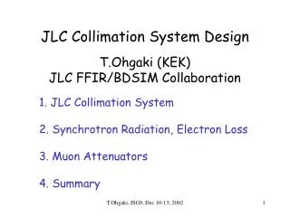
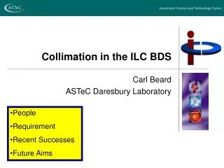
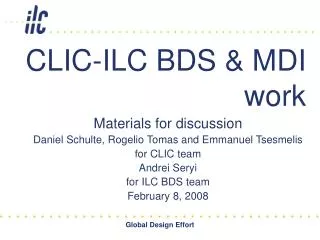
Effect of MDI Design on BDS Collimation Depth. Frank Jackson ASTeC Daresbury Laboratory Cockcroft Institute. Contents. Collimation depth and method RDR collimation depth (SiD MDI) Other MDIs (GLD, GLC) Other parameter sets. Collimation Depth Philosophy.

E N D
Effect of MDI Design on BDS Collimation Depth Frank Jackson ASTeC Daresbury Laboratory Cockcroft Institute ILC-GDE Meeting Beijing Feb 2007
Contents • Collimation depth and method • RDR collimation depth (SiD MDI) • Other MDIs (GLD, GLC) • Other parameter sets ILC-GDE Meeting Beijing Feb 2007
Collimation Depth Philosophy • Halo synchrotron radiation (SR) from final doublet must pass cleanly through interaction region (IR) • Small apertures in the IR include vertex detector, masking, forward calorimetry, extraction quadrupoles • Halo size & divergence at final doublet entrance must be constrained to ‘collimation depth’ • Effective collimation depth (actual spoiler gaps) may need to be tighter to compensate for spoilerFD transport ILC-GDE Meeting Beijing Feb 2007
Collimation Depth Method • Possible to solve problem analytically • SR fan profile through detector depends on halo size in FD • Halo size in FD depends on collimation aperture • Constrain SR fan size to solve for collimation depth • Many SR emission points • No unique solution; solution ellipse in x, y IR Aperture SR fan profile y s Collimated beam halo x ILC-GDE Meeting Beijing Feb 2007
Implementing the Method • Analytical method implemented by O. Napoly (Saclay) for TESLA TDR (2001) • Calculates the solution ellipses from very many SR emission points through whole FD • Halo phase space at each emission point is reverse-traced (linear, on-energy optics) from IP. • Repeat analysis for each small IR aperture • Find global collimation depth vtx beamcal mask ILC-GDE Meeting Beijing Feb 2007
2006c beamcal & low-Z mask RDR collimation depth • IR design assumes SID-like detector, L* = 3.51 • Collimation depth constraint comes from first extraction quad (R= 15mm) • Beamcal mask (r=12mm) comes close to SR fan • 11.9x , 70.7y spoiler full gaps 2.7mm (x) 1.3mm (y) 2006e ILC-GDE Meeting Beijing Feb 2007
MDI Impact on Collimation Depth • MDI depends on final detector concept • Effect of changing MDI on IR parameters • L* • Forward calorimetry geometry • Extraction line design • (possibly) final quad changes • Difficult to evaluate the effect of change in MDI on collimation depth • Complete MDI designs don’t exist for all the concepts ILC-GDE Meeting Beijing Feb 2007
MDI parameter space • Need complete MDI parameter set to calculate each collimation depth • Used detector outline docs to get information (red means guess) • Extraction quad QEX is the limiting aperture in all cases • But my QEX guesses are very uncertain for LDC and GLD • Results show expected - SR fan size at a fixed point from IP increases with L* (for fixed FD) ILC-GDE Meeting Beijing Feb 2007
Parameter Sets • Calculation has been done for nominal parameter set • Other parameter sets have smaller * larger IP angles tighter collimation • ‘Low P’ & ‘high lumi’, * twice as small as nominal • Reduced collimation depth by factor 1/2 • ~ 8.5x , 50y ILC-GDE Meeting Beijing Feb 2007
QD QD Alternative Crossing Angles? • 2mrad remains alternative ‘small angle’ option • Lack of symmetry in problem, shared magnets for incoming/extracted beam • Force symmetry by using ‘virtual apertures’ that ensure SR clearance incoming beam axis detector axis 1.0mrad 2.0mrad outgoing beam axis ILC-GDE Meeting Beijing Feb 2007
Conclusion • Latest extraction line design now constrains collimation depth • Impossible to say which is the best detector concept for collimation, without complete MDI design (inc. extraction line) for each concept. • Greater L* will probably lead to tighter collimation • Philosophy has been for perfect clean SR passing through IR • More sophisticated analysis • Can we tolerate SR on the extraction quads and beamcal – and so relax collimation depths • The answer to those questions will be strongly affected by MDI design. ILC-GDE Meeting Beijing Feb 2007
Backup Slides ILC-GDE Meeting Beijing Feb 2007
SID Concept Geometry • L*=3.51 m • BeamCal inner radius 15mm (p28, last para) • BeamCal Beampipe inner radius 12 mm (Fig 80, p131) • BeamCal LowZ covering mask radius 12mm (for 20 mrad, p160) • BeamCal Z location 321-334 (Table 1, p13) • Vertex beampipe radius 12mm (fig 29, p 53) • Much of the beamcal geometry worked out for 20 mrad, hope it is same for 14 mrad ILC-GDE Meeting Beijing Feb 2007
GLD Concept Geometry • L* = 4.5 m (first para, p96) • BeamCal inner radius 20mm (Tab 2.13, p 97) • BeamCal Beampipe inner radius 15mm (Tab 3.1, p104) • BeamCal LowZ covering mask radius 20mm (Tab 2.13, p 97) • BeamCal Z location 430-450 (2nd para, p73) • Vertex beampipe radius 15mm (first para, p 96) • Much of the beamcal geometry worked out for 20 mrad, hope it is same for 14 mrad ILC-GDE Meeting Beijing Feb 2007
LDC concept • L* = 4.05 m (p98) • BeamCal inner radius 13mm (Tab 6, p 9) • BeamCal Beampipe inner radius ??? • BeamCal LowZ covering mask ???? • BeamCal Z location 355-375 (Tab 6, p 9) • Vertex inner radius (not beam pipe) 16mm (Table 1, p8) • Much of the beamcal geometry worked out for 20 mrad, hope it is same for 14 mrad ILC-GDE Meeting Beijing Feb 2007
GLD extraction geometry • Justification for my guess at extraction line params on slide 8. • Slide from Valencia meeting T. Tauchi ‘Background Study at GLD-IR’ • Has used 2006c deck designed for L*=3.51 • Changed QD0 position to L*=4.5, • But no changes to extraction quads position & aperture ILC-GDE Meeting Beijing Feb 2007
Off-Energy Halo? • DBLT routine uses linear, on-energy beam transport • Can cross check with BDSIM simulation • Off-energy, collimated halo (p = 1% Gaussian), at FD entrance, track and plot resulting SR fan • Plot below are for 2006c lattice SR profile at 1st Extraction Quad (r=18mm) p=1%, Gaussian On-energy, p=1% Gaussian ILC-GDE Meeting Beijing Feb 2007
1TeV Parameters • IP angle = Sqrt(e/b) • From 500GeV to 1TeV, e2e, bx1.5bx, by0.75by • IP angle in y more than doubles • Collimation depth twice as tight in y. ILC-GDE Meeting Beijing Feb 2007