Download
1 / 2
20 likes | 159 Vues
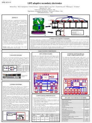
Configuration (CCD type, number of subapertures). Number of channels (each mirror). Bandwidth. CCD readout time ( µs ). - 3dB @ 90 KHz. Slopes computer latency after end of CCD readout ( µs ). Real time comm. slopes transfer from BCU to AM2-RTR ( µs ). RTR (zonal) + FeedForward( µs ).

E N D
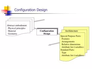
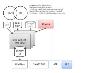
Configuration (CCD type,number ofsubapertures) Number of channels (each mirror) Bandwidth CCD readout time ( µs ) - 3dB @ 90 KHz Slopes computer latency after end of CCD readout ( µs ) Real time comm. slopes transfer from BCU to AM2-RTR ( µs ) RTR (zonal) + FeedForward( µs ) 672 Total time from CCD frame to M2 start ( µs ) Noise Number of DSP boards 2.4 nm rms 84 RTR (modal) + FFWD ( µs ) Thermal stability Channels controlled by every board 0.15 nm/°K 8 CCD 39 30x30 800 0 20 44 864 Power dissipation Number of backplanes 78 mW 6 (3 crates) 57 877 DSP boards on each crate 14 CCD 60 30x30 256 132 20 44 452 Type of DSP ADSP-21160 57 465 Computational performance (single DSP) (32x32 bit 40 bit, floating point Multiply and Accumulate operations per second – MAC/s) 180 MegaMAC/s Total computational power (one mirror) 60 GigaMAC/s Actual real time communication data throughput 2.9 Gbit/s Actual diagnostic communication data throughput 400 Mbit/s Capacitive sensor bandwidth -3dB @ 90 KHz Current driver bandwidth -3dB @ 56 KHz Power dissipation in the crates (=0.55µm, r0=0.15m, mirror thickness=1.6mm, coil efficiency 0.5 N/W) 2541 W Power dissipation in the actuators (coil + capacitive sensor, same as above)) 124 W Total power dissipation 2665 W Power supply voltage ±48V @ 30 A SPIE 4839-91 LBT adaptive secondary electronics Roberto Biasi a, Mario Andrighettoni a, Daniele Veronese a, Valdemaro Biliotti b, Luca Fini b, Armando Riccardi b, P.Mantegazza c, D.Gallienid a Microgate S.r.l. - Italy b Osservatorio Astrofisico di Arcetri - Italy c Dipartimento di Ingegneria Aerospaziale - Politecnico di Milano - Italy d ADS International S.r.l. - Italy ABSTRACT The adaptive secondary mirror is a fundamental part in the LBT adaptive optics architecture. The thin, continuous mirror is controlled by 672 electromagnetic actuators (voice coil motors) with local position feedback (capacitive sensor) and allows to perform from tip-tilt to high order wavefront correction, but also chopping. The adaptive secondary is controlled by a DSP-based dedicated electronics. The control electronics does not only implement the mirror position control tasks, but does also realize the Real Time Reconstructor (RTR). The control system, while maintaining a similar architecture to the MMT adaptive secondary one, shows a substantial enhancement in terms of computational power, rising in the range of hundreds of Gigaflops. This allows to minimize the computational time required to apply the wavefront correction pattern from the wavefront sensor acquisition, even in case of high order reconstructor dynamics. The electronics is housed in compact cooled crates placed in the adaptive secondary hub. Apart from the power supply lines, it is connected to the other components of the adaptive control system just through a very high speed fiber optic link, capable of 2.9 Gigabit/s of actual data throughput. The control system has been designed according to modular concept, so that the number of channels can be easily increased or reduced for adapting the electronics to different correctors. A substantial effort has been dedicated to the flexibility and on-field configurability of system. In this frame, the same electronics (or part of it) can be easily adapted to become the building block for the data processing unit required for Multi-Conjugated Adaptive Optics. Keywords: Adaptive optics, real time control system, parallel computation, deformable mirrors, adaptive secondary. CONTROL ELECTRONICS OVERVIEW The Adaptive secondary mirror is controlled by 672 identical actuators, each embedding the voice coil motor that applies a local force to the mirror (without any mechanical contact) and the signal conditioning circuit for the capacitive sensor that senses the gap between reference body and thin shell. The actuators are connected to signal distribution boards, placed immediately behind the coldplate. The signal distribution boards provide the connection to the DSP control boards. Each of these controls 8 channels by means of 4 floating point DSPs. Every backplane (there are 6 backplanes in the system, arranged into 3 liquid cooled crates) contains 14 control boards, one signal generation board providing a stable reference signal for the capacitive sensors, and a communication board that implements the high speed, real time communication between slope computer and adaptive mirror. Moreover, the communication board provides a diagnostic communication line over a standard Ethernet connection. All boards have identical size (191x96 mm). Due to the high complexity and large number of components mounted on them, the boards implement the most recent Surface Mounting Technology (SMT), with a large number of components in Ball Grid Array (BGA) package. MAIN SYSTEM COMPONENTS CAPACITIVE SENSORS The capacitive sensor provides the measurement of the local gap between the reference body and the thin shell. The measurement is obtained by demodulating in amplitude a reference signal which is amplified by an AC-coupled inverting amplifier, which gain is roughly inversely proportional to the gap to be measured. With respect to the MMT electronics, the capacitive sensor has been significantly improved, while maintaining the same operating principle. In particular, the new capacitive sensor embeds an analog de-modulator, that allows to improve the sensor bandwidth. DSP CONTROL BOARDS Each DSP control board controls eight actuators on the adaptive secondary mirror. The board comprehends a high speed digital part (DSP, diagnostic processor and communication electronics) and an analog front-end that interfaces the board to the actuators and capacitive sensors. The system logic is based on the last generation Altera Stratix CPLD device. The logic handles the communication between the parallel backplane and the four DSPs on the board, and embeds a processors for board diagnostic. The real time control tasks are performed by the four DSPs (ADSP-21160 floating point unit), each controlling two channels. Every DSP is connected to two 16 bit ADCs, that performs the conversion of the capacitive sensor output, and to two DACs controlling the current driver for the Voice Coil Motors on the actuators. In addition to the digital control loop, an analog derivative loop provides a direct feedback between the capacitive sensor analog output and the current driver input. This circuit provides an efficient electronic damping to allow fast mirror response with large mirror/reference plate gaps. COMMUNICATION BOARDS and BASIC COMPUTATIONAL UNIT The communication with the adaptive secondary control system is a very critical aspect of the overall system design.We can distinguish two separated communication links: real time communication and diagnostic communication. The real time communication carries only the data related to the adaptive optics control loop: it transfers the slopes from the slope computer to the adaptive secondary control system and allows to exchange intermediate computational results for reconstructor algorithms implementing IIR filter (e.g. time-dependent modal reconstructors).The real time communication interface is based on the Fiber Channel physical layer, with an actual data throughput of 2.9 Gbit/s. Real time communication is handled only by hardware and provides direct DMA access to the memory of all DSPs in the system, without any software overview. The diagnostic communication is used to transfer all diagnostic data (circular buffers, boards status) and for system maintenance. The external interface is based on the Gigabit Ethernet standard. Within the LBT adaptive secondary electronics, the communication functions are accomplished by dedicated boards that also embed a local processing power (ADSP-21160). These boards can be also used for other applications within the adaptive optics system, like slope computations or merging of data acquired by different wavefront sensors in a Multi-Conjugate adaptive optics system. Principle of operation Performances (experimental data) Capacitive sensor board (actual size:95x10 mm) and actuator CONTROL SOFTWARE Within the adaptive secondary software architecture, we can distinguish two different layers, namely the control software and the diagnostic software. The control software comprehends the high speed local control loop, that implements a local position controller, and the global computations required to implement the Real Time Reconstructor and the feed-forward technique. The local control loop senses the gap between thin shell and reference plate through the capacitive sensor. The information is first linearized, then the error with the required position is fed into the digital control filter (typically a Proportional Derivative controller). This part of the control software runs at 80 KHz (12.5µs cycle time). The global computations are performed each time a set of slopes becomes available from the slope computer. Different Reconstructor typologies can be implemented in the system (zonal, modal, time-dependent), as MIMO IIR filters. All these computations can be very effectively performed by the parallel architecture of the adaptive secondary control system. In fact, every DSP can execute only the operations related to the two controlled channels, involving just two rows of the gain matrices. Efficient communication primitives are available for data exchange. The diagnostic software allows the acquisition of circular buffers and permits an easy implementation of calibration and test procedures. Following the guideline of the MMT system, the diagnostic code running on the DSPs provides a very flexible and powerful structure for reading and/or writing data vectors synchronously with the fast local loop, leaving to the Adaptive Optics Supervisor software the actual definition of the diagnostic parameters. COMPUTATIONAL PERFORMANCES LBT ADSEC ELECTRONICS IN NUMBERS To give an estimate of the control system computational performance, we considered some real configurations: • LBT first light: CCD 39, 80x80 pixel, no binning, 30x30 subapertures, off-the-shelf SciMeasure Analytical Systems acquisition board (4 pixels x 12 bits parallel acquisition @ 2 MHz = 8 Mpixel/s) • CCD 60, 128x128 pixel, 2x2 binning, 30x30 subapertures, acquisition board by Osservatorio di Arcetri (under development), with fiber interface (1 pixels x 16 bits @ 16 MHz = 16 Mpixel/s) The slopes are computed by a single BCU. Their computation starts once half of the pixels have been acquired from the CCD. This explains the null time required for the first configuration. The RTR and feedforward computations take into account the load of the fast real time control loop and of the diagnostic tasks. The reconstructor algorithms considered implement a dynamic filter with a single pole (pseudo-integrator) for both the zonal and the modal case.
SPIE 4839-90 LBT adaptive secondary units final design and construction D.Gallieni *a, E.Anaclerio a, P.G.Lazzarini a, A.Ripamonti a, R.Spairani b, C.DelVecchio c, P.Salinari c, A.Riccardi c, P.Stefanini c, R.Biasi d a ADS International S.r.l. (Italy); b SOLARIA Engineering (Italy); c Osservatorio Astrofisico di Arcetri (Italy); d Microgate S.r.l. (Italy) ABSTRACT The Large Binocular Telescope will perform its first level AO correction at visual wavelengths by the two Gregorian secondary mirrors. Each unit is made by a 911 mm diameter and 1.6 mm thick Zerodur shell which shape is controlled by 672 electromagnetic actuators at 1 kHz rate. The shape of each mirror is referred to a Zerodur 50 mm thick backplate through a set of capacitive sensors co-located with the actuators. Each adaptive secondary unit embeds its real time computer for actuator control and communication. Each unit is aligned into the secondary hub by a 6 d.o.f. hexapod system. The construction of the AO units started this year, while the hexapods have been completed in 2001. We present in this paper the final design of the adaptive secondary systems with particular emphasis on the modifications that we made based on the MMT adaptive secondary experience. We will also report the first results of the subsystems development tests. Keywords: adaptive optics, deformable mirror, adaptive secondary mirror, electromagnetic actuators, Large Binocualr Telescope MMT336 adaptive secondary during installation at the telescope (left); comparison of LBT and MMT adaptive secondary, true scale rendering (right). • FROM MMT336 TO LBT672: DESIGN UPGRADES • COOLING SYSTEM. The most evident failure on the MMT336 was the leakage of the cooling system of the actuators mounting plate. This plate was actually made of two aluminum disks glued together: grooves were cut on one of the glued surfaces to make the cooling channels. This problem is now addressed on the LBT672 design by making the cooling lines by mounting copper pipes on the aluminum plate. • GAP CONTAMINATION. The contamination of the 50 mm gap between the deformable mirror and the reference plate forced stopping the MMT336 quite often for inspection and cleaning. We discovered that the path for the dust is to enter the gap through the reference plates holes where are located the actuators. For this reason, on the LBT672 mirrors we have foreseen placing soft gaskets around each actuator head (close to the coil) to seal the reference plate hole. • ACTUATOR MOUNTING & HARNESS ROUTING. A major modification of the MMT336 design was taken to simplify the harness between the actuators and the electronic crates. It was decided to have a layer of “distribution boards” installed on top of the actuators mounting plate and to insert the actuators from the mirror side. The PCB aboard each actuator plugs into a socket of the “distribution board”, which provides both power and signal connections. The “distribution boards” are then connected to the crates by flat cables, each one serving eight actuators, thus reducing the overall harness volume and complexity. • CAPACITIVE SENSOR ARMATURES AND CONTACTS. For the LBT reference plate we moved to a chemical coating method that gives a thick and solid (not scratched) conductive surface. Moreover, with this method the capacitive sensor contacts can be remoted inside the reference plate hole, freeing the radial gap between the magnet and the reference plate. Finally the electronic board holding the contacts is now rigidly connected to the actuator rod, avoiding any movement of the board itself. Actuator new mounting system schematics. The actuator is inserted into the mounting plate through the reference plate. The capacitive sensor PCB plugs into the socket on the distribution board. • SINGLE ACTUATOR PROTOTYPE TEST RESULTS • A test bench with a single actuator was set up to proof the effectiveness of the novel design of the mounting system and to measure the actuator efficiency. • The mechanical design was tailored and validated. • The electromagnetic efficiency measured on the baseline coil design (12mm OD, 4mm ID and 3mm height) was 0.5 Newton/sqrt(Watt). Further tests on modified coil design showed that: • increasing the coil inner diameter from 4 mm to 6 mm makes the efficiency dropping by about 10 %; • the outermost layers in the coil plays a significant role: the efficiency reduces by 5% removing the outermost three coil layers. • finally, all the measurements gave a consistent proof of the electromagnetic efficiency relation with the air gap, that is of the order of 5% per 0.1 mm gap variation. The actuator thermal resistance between the coil and the cold plate was measured being of the order of 5.5 K/Watt. The 6mm ID coil resulted more efficient from the thermal point of view than the 4mm ID one, thus giving better global performances. Moreover, such a coil can be also more easily winded and therefore can be preferred to the baseline 4 mm one. Finally, the thermal impedance between the coil and the mirror front was measured to be actually twice as the one toward the cold plate. Actuator coil bobbin and permanent magnet details. The coil is made by 0.18mm wire and its resistance is 4 W. The magnet is made by eight radial sectors plus a central bias one. Actuator electromagnetic and thermal efficiency test results. LBT672 CONSTRUCTION SCHEDULE The design and prototyping activity to prepare the LBT adaptive secondary construction has been completed in Spring 2002. The major modifications adopted with respect to the MMT336 unit design are concerned with the actuator design. This has been validated through the single actuator prototype. The construction of a 45 actuators Engineering Model is under way and its electromechanical and optical testing is planned for the Winter 2002-Spring 2003. The construction of the two LBT672 adaptive secondary mirrors is scheduled for year 2003, with the electromechanical testing of the first unit planned for late 2003-Spring 2004.