Logic Design Dr. Yosry A. Azzam
520 likes | 1.24k Vues
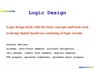
Logic Design Dr. Yosry A. Azzam. Binary systems. Chapter 1. Agenda Binary Systems : Binary Numbers, Binary Codes, Binary Logic ASCII Code (American Standard Code for Information Interchange) Boolean Algebra (Basic Theorems, Property of Boolean Algebra, Boolean Functions) Logic Gates.

Logic Design Dr. Yosry A. Azzam
E N D
Presentation Transcript
Logic Design Dr. Yosry A. Azzam
Binary systems Chapter 1
Agenda Binary Systems :Binary Numbers, Binary Codes, Binary Logic ASCII Code (American Standard Code for Information Interchange) Boolean Algebra(Basic Theorems, Property of Boolean Algebra, Boolean Functions) Logic Gates Readings Mano: Ch 1 & 2 (until 2-4) Objectives Understand Bit & Byte as the foundation of data representation Understand the Binary System, it’s operations, conversions and negative number representation Understand the Logic Gates & Binary Logics, which they based on
Data Representation • The complex computer system is built on a 2-states system (on/off) : The Binary System. • Binary system is a 2 base numbering system: 0 and 1 • Each 0 and 1 is called “BIT” (BInary digiT)
Bit (0 or 1) Off/On for positive logic On/Off for negative logic Dec (Bin) 0 (0000) 1 (0001) 2 (0010) 3 (0011) 4 (0100) 5 (0101) 6 (0110) 7 (0111) Bits & Bytes • 8 (1000) • 9 (1001) • 10 (1010) • 11 (1011) • 12 (1100) • 13 (1101) • 14 (1110) • 15 (1111)
Byte : a group of 8 bits, represent : ASCII characters(1 byte is 1 character) Refer to ASCII Table p : 23 Unicode There are other format of data representation discussed later in the course. A (0100 0001) B (0100 0010) … Z (0101 1010) … 0 (0011 0000) 1 (0011 0001) … 9 (0011 1001) Bits & Bytes (cont’d)
Binary Systems • Binary Numbers • Binary Codes • Binary Logic
Binary and Decimal Numbers • Binary • 1010 = 1x23 + 0x22 + 1x21 + 0x20 • 0, 1, 10, 11 … • Called “Base-2” • Decimal • 7392 = 7x10³ + 3x10² + 9x101 + 2x100 • 0, 1, 2, 3, 4, 5, 6, 7, 8, 9, 10, 11 … • Called “Base-10” • Octal • Based-8 : (0, 1, 2, 3, 4, 5, 6, 7) • Hexadecimal • Based-16 : (0, 1, 2, 3, 4, 5, 6, 7, 8 ,9 ,A ,B ,C ,D ,E ,F) Reading : Mano. Chapter 1
Binary Systems and Number Base Conversion:Decimal Numbers (Base-10): 0,1,2,3,4,5,6,7,8, and 9 Ten DigitsBinary Numbers (Base-2): 0 and 1 Two DigitsOctal Numbers (Base-8): 0..7 Eight DigitsHexadecimal No. (Base-16): 0,…,9,A,B,C,D,E,F 16 Digitsand so on.
1.3 Number Base Conversion(1): (7392)10 = 7x10³ + 3x10² +9x101 +2x100(2): (1010.011)2 = 1x23 +0x22 +1x21 +0x20 +0x2-1 +1x2-2 +1x2-3 =(10.375)10(3): (4021.2)5 = 4x53+0x52+2x51+1x50+2x5-1 = (511.4)10(4): Convert decimal 41 to binary, i.e., (41)10 = ( ¿?)2 Solution:
(5): Convert (0.6875)10 to binary. • Answer: (0.6875)10 = (0.1011)2
(6): Convert decimal 153 to octal, i.e., (153)10 = ( ¿?)8 Solution: (153)10 = ( 231)8
(7): Convert (0.513)10 to octal, to seven significant figures Answer: (0.513)10 = (0.406517…..)8
(8): Convert decimal 153.513 to octal,since we know that (153)10 = ( 231)8and (0.513)10 = ( 0.406517)8Then (153.513)10 = ( 231.406517)81.4 Octal and Hexadecimal NumbersSince 23=8 and 24=16, each octal digit corresponds to three binary digits and each hexadecimal digit corresponds to four binary digits.Examples:convert the binary 10110001101011.111100000110 to octal.Answer: (10 110 001 101 011 . 111 100 000 110)2 = ( 2 6 1 5 3 . 7 4 0 6 )8convert the binary 10110001101011.111100000110 to Hexadecimal Answer: (10 1100 0110 1011 . 1111 0000 0110)2 = ( 2 C 6 B . F 0 6 )16
Binary Numbers : Conversions 2 • Octal (23 = 8) • (10110001101011.111100000110)2 • (26153.7406)8 • Hexadecimal (24 = 16) • (10110001101011.111100000110)2 • (2C6B.F06)16 10 110 001 101 011.111 100 000 110 2 6 1 5 3 . 7 4 0 6 10 1100 0110 1011.1111 0000 0110 2 C 6 B . F 0 6
Summation Multiplication Subtraction Binary Numbers : Operations 101101 +100111 ---------- 1010100 101101 -100111 ---------- 000110 1011 101 ---------- 1011 0000 . 1011 . . ---------- 110111
Diminished Radix Complements • Complements are used in digital computers for simplifying the subtraction operation and for logical manipulation. • Given a number N in base r having n digits, the (r-1)’s complement of N is defined as (rn -1) –N • For decimal numbers, r = 10 and r-1 =9 So, • The 9’s complement of N is (10n -1)-N = 999..99-N • For binary numbers, r=2 and r-1=1 so, • The 1’s complement of N is (2n-1)-N=111…111-N
Radix Complements • The radix complement of an n-digit number N in base r is defined as rn-N for N≠0 and 0 for N=0. i.e. the radix complement= diminished radix complement +1
Complements • The complement of 012398 is • 9’s complement (diminished radix complement) • (999999)10-(012398)10 = (987601)10 • 10’s complement (radix complement) • (987602)10 = (987601)10 + 1=(987602)10 or: • (1000000)10-(012398)10=(987602)10 • The complement of 1101100 is • 1’s complement (diminished radix complement) • (1111111)2- (1101100)2= • 2’s complement (radix complement) • (10000000)2- (1101100)2= 0010011 0010100
Complements (cont’d.) • The (r-1)’s complement of octal or hexadecimal numbers is obtained by subtracting each digit from 7 or F (decimal 15) respectively
Examples: (1): 10’s complement of (52520)10 = 105 – 52520 =47480 (2): 10’s complement of (246700)10 is 753300 (3): 10’s complement of (0.3267)10 = 1.0-0.3267 = 0.6733 (4): 2’s complement of (101100)2=(26)10-(101100)2=(1000000)2-(101100)2 =(010100)2 (5): 2’s complement of (0.0110)2=(20)10-(0.0110)2=(1-0.0110)2 =(0.1010)2.
Subtraction with Complement 72532 10’s complement: +96750 --------- Sum: 169282 Remove end carry: -100000 --------- Answer: 69282 • 10’s complement • Subtract 72532 – 3250 • 2’s complement • Subtract 1010100 - 1000011 1010100 2’s complement: +0111101 --------- Sum: 10010001 Remove end carry: -10000000 --------- Answer: 0010001
Signed Binary Numbers 1 • Due to hardware limitation of computers, we need to represent the negative values using bits. Instead of a “+” and “-” signs. • Conventions: • 0 for positive • 1 for negative
Signed Binary Numbers 2 • (9)10 = (0000 1001)2 • 1. Signed magnitude (used in ordinary arithmetic): • (-9)10 = (1000 1001)2 • Changing the first “sign bit” to negative • 2. Signed 1’s complement: • (-9)10 = (1111 0110)2 • Complementing all bits including sign bit • 3. Signed 2’s complement: • (-9)10 = (1111 0111)2 • Taking the 2’s complement of the positive number
Arithmetic Addition and Subtraction +6 00000110 +13 00001101 +19 00010011 - 6 11111010 +13 00001101 +7 00000111 + 6 00000110 - 13 11110011 - 7 11111001 - 6 11111010 - 13 11110011 - 19 11101101
Binary Logic • Binary Logic: Consists of Binary Variables and Logical Operations • Basic Logical Operations: • AND • OR • NOT • Truth tables: Table of all possible combinations of variables to show relation between values
Logical Operation: AND • Value “1” only if all inputs are “1” • Acts as electrical switches in series • Denote by “. ”
Logical Operation: OR • Value “1” if any of the inputs is “1” • Acts as electrical switches in parallel • Denote by “+”
Logical Operation: NOT • Reverse the value of input • Denote by complement sign ( !x or x’ or x ). • Also called “inverter”
Logic Gates • Is electronic digital circuits (logic circuits) [Mano p.29-30] • Is blocks of hardware Called “digital circuits”, “switching circuits”, “logic circuits” or simply “gates”
Volts 4 Logic 1 3 2 1 0.5 Logic 0 0 -0.5 Binary Signals Levels • Acceptable levelof deviation • Nominal level • State of transition
BCD Code • Although the binary number system is the most natural system for a computer, most people are more accustomed to decimal system. • Convert decimal numbers to binary, perform all arithmetic calculations in binary and then convert the binary results back to decimal. • So, we represent the decimal digits by means of a code that contains 1’s and 0’s. • Also possible to perform the arithmetic operations directly with decimal numbers when they are stored in coded form.
BCD Code • Ex1: BCD for (396)10 is (0011 1001 0110)BCD • Ex2: (185)10=(0001 1000 0101)BCD = (10111001)2 • So, the BCD has 12 bits, but binary equivalent has 8 bits
BCD Addition • 4 0100 4 0100 8 1000 + 5 0101 +8 1000 +9 1001 9 1001 12 1100 17 10001 + 0110 + 0110 1 0010 1 0111 Binary Carry 1 1 0001 1000 0100 184 +0101 0111 0110 +576 Binary sum 0111 10000 1010 Add 6 0110 0110 BCD sum 0111 0110 0000 760
Decimal Arithmetic of BCD • Add (+375) + (-240)= +135 0 375 Complement of 240 + 9 760 Discard the end carry 0 135 The 9 in the leftmost position of the second number represents a minus
ASCII Character Code • The ASCII (American Standard Code for Information Interchange) • 7 bits per character to code 128 characters including special characters ($ = 0100010) • It uses 94 graphic characters that can be printed and 34 non-printing characters used for control functions. • There are 3 types of control characters: format effectors, information separators, and communication control characters.
ASCII Character Code (Contd.) • Although ASCII code is a 7-bit code, ASCII characters are most often stored one per byte. • The extra bit are used for other purposes, depending on the application. • For Ex., some printers recognize 8-bit ASCII characters with the MSB set to 0. • Additional 128 8-bit characters with the MSB set to 1 are used for other symbols such as the Greek alphabet or italic type font.
Error Detecting Code • To detect errors in data communication and processing, the eighth bit is used to indicate parity. • This parity bit is an extra bit included with a message to make the total number of 1’s either even or odd. with even parity with odd parity • Ex: ASCII A = 1000001 01000001 11000001 ASCII T = 1010100 11010100 01010100
The ASCII codes for the letters A and F adjusted for odd parity