K ansas L ight S ource Laser System
320 likes | 508 Vues
K ansas L ight S ource Laser System. J. R. Macdonald Laboratory Department of Physics, Kansas State University September, 2010. Kansas Light Source: Amplified Ti:Sapphire Laser System. Amplifier. KLS output. Multi-pass Ti:Sapphire Amplifier. Mode-Locked Ti:Sapphire Oscillator.

K ansas L ight S ource Laser System
E N D
Presentation Transcript
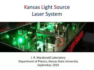
Kansas Light Source Laser System J. R. Macdonald Laboratory Department of Physics, Kansas State University September, 2010
Kansas Light Source: Amplified Ti:SapphireLaser System Amplifier
KLS output Multi-pass Ti:Sapphire Amplifier Mode-Locked Ti:Sapphire Oscillator 4 W Average Power 27 fs Pulse Width 2 KHz Repetition Rate 2 mJ Pulse Energy 780 nm Central Wavelength 40 nm Bandwidth 350 mW Average Power 12 fs Pulse Width 80 MHz Repetition Rate 5 nJ Pulse Energy 800 nm Central Wavelength 95 nm Bandwidth
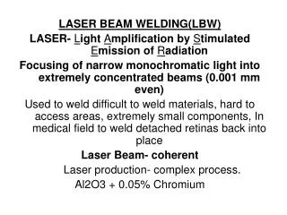
Light Amplification by Stimulated Emission of Radiation Pump Cavity mirror Cavity mirror/output coupler Laser medium Laser output Optical cavity→ LASER
Interaction of light with matter In laser medium • Spontaneous • emission • Stimulated • emission Absorption Population inversion → LASER
Ti:Sapphire crystal Ti3+:Al2O3
CPA stretcher/compressor Positive Dispersion Negative Dispersion
Infrared Filter BBO I2(t) I1(t) M6 spectrometer Translation Stage M3 M5 M2 M4 From Laser M1 BS FROG: Beam Diagnostic
KLS system timing Delay Generator SRS 645 Pump1 Pump2 PC1 PC2 CEP Control Menlo System 2kHz PD1 80 MHz Oscillator PC1 PC2 PD2 PD3 PD4 Oscilloscope
KLS subsystems and devices Oscillator: pump laser, crystal chiller, photo diode, Menlo timing controller Amplifier: crystal chamber and vacuum pump, liquid nitrogen controller, Dewar, delay generator, pockels cells, pockelscell power supplies, pump lasers, pump laser power supplies, pump laser control computers, pump laser chillers, photo diodes, oscilloscope, power meter, power monitor, power locking PID (proportional–integral–derivative) controller, spectrometer, spectrometer computer FROG: spectrometer, spectrometer computer, CCD camera, FROG computer Other: power meters, mobile spectrometer, IR viewer, IR cards
Optics Coated Mirrors (metal or dielectric): reflectivity, phase, bandwidth, damage threshold Beamsplitters: dielectric coating, reflectivity and transmission, phase, bandwidth, damage threshold Lens and windows: coating, material, thickness Wave plates: coating, material, thickness Polarizer Chirped mirror and compensation plates Gratings and prisms Nonlinear optical crystals
Safety Wear your goggles Know where the beam goes Do not put your eyes at the beam height Contact Kun Zhao (Harry) Baozhen Zhao Al Rankin
Chromatic and Astigmatism Aberrations Of a Lens
Birefringence and Wave Plate Half-wave plate
Stretcher CEP Lock PC1 Seed Femtolaser oscillator Verdi-6 Evolution 30 Pump Pump Evolution 30 Amplifier Compressor PC2 Final Output
5µs Channel Timer BNC 555B A B C D Pump1380 Pump2302 PC11900 PC21940 CE Control Menlo System System Timer BNC 555A f/16 2V f/45 10ns 75 MHz, 1V KLS TimingJan 15, 2005 PD1 CE measure f/4 Oscillator PC1 PC2 Pulse Generator Philips PM5712 PD2 PD3 PD4 1.5 V, jitter 1 ns to Experiment 75M-1kHz 400 mV 1 kHz 150 mV 1 kHz, 1V Oscilloscope Tek TDS3054
Laser Metrics 5046 Laser Metrics 5046 INPUT INPUT 7.5 kV HV Adj 7.5 kV HV Adj HV Bias HV Bias Q-SW CW Q-SW CW Trig Delay Width MON Outputs Trig Delay Width MON Outputs Pockels Cell 1 Long cable delay goes to control room Pockels Cell 2 76 MHz kHz DG535 Pump1: A: 510 ns; B: A + 5 s Pump2: C: 310 ns; D: C + 5 s Delay Unit: > 1 us PC1:Delay 55 ns; Width 10 ns PC2:Delay 45 ns; Width 10 ns Delay DG535 Photo Diode OUT IN 0 AB CD Master kHz signal is generated by DG535. PC1 is trigged by the kHz laser signal selected by the master signal and the signal from the photo diode. PC2 is trigged by the MON signal from PC1. Long cables are used for PC1 to compensate the trig delay of PC2 Pump1 Pump2