Large Deformation Non-Linear Response of Composite Structures
270 likes | 430 Vues
Large Deformation Non-Linear Response of Composite Structures. C.C. Chamis NASA Glenn Research Center Cleveland, OH L. Minnetyan Clarkson University Potsdam, NY. Invited Presentation for Innovative Solutions to Challenging Problems NASA Workshop on FEM & FEA Goddard Space Flight Center

Large Deformation Non-Linear Response of Composite Structures
E N D
Presentation Transcript
Large Deformation Non-Linear Response of Composite Structures C.C. Chamis NASA Glenn Research Center Cleveland, OH L. Minnetyan Clarkson University Potsdam, NY Invited Presentation for Innovative Solutions to Challenging Problems NASA Workshop on FEM & FEA Goddard Space Flight Center Greenbelt, MD - May 18, 2000
Presentation Outline • Background • Objective • Approach • Applications • Composite panel fracture • Composite shell-burst • Composite containment • Composite pre-forms manufacturing • Summary
Progressive Fracture Under Cyclic Load(Experimental Data: Mandel, et al)
Objective • Describe a non-traditional computational simulation method/computer code to a variety of non-linear structural responses
What is This Non-Traditional Computational Method? • Bottoms-up synthesis for structural behavior/response • Telescoping composite mechanics • Top-down decomposition for local effects • Progressive substructuring • Nodal-base finite element formulation • Progressive structural fracture • Incremental linear updating • Multi-factor interaction material behavior model • Node(s) - by - node(s) un-zipping • Integrated into a seamless computer code (CODSTRAN)
Multi-Scale Hierarachical SimulationComputational Simulation: Recursive A;;lication of Laminate Theory
CODSTRAN Damage Tracking - Representative Points 1. Equilibrium - no damage 2. Initial damage: degrade properties 3. Damage accumulation: more degradation 4. Damage stabilization: no additional damage 5. Damage propagation
Composite Structural Performance Evaluation Summary • Structural Analysis Model (SAM) • Where: • Solution of SAM: • Structural Integrity • Fatigue and Life • Structural Durability • Structural Reliability
Compressive Load with End DisplacementAS-4/HMHS[[0/±45/90]s]6
Pressurized Cylindrical ShellsGraphite/epoxy laminated compositeVf = 0.60; Vv = 0.01; Tcu = 177°C (350°F) • In all cases damage initiation was my matrix cracking due to transverse tensile stresses in 0° plies. • For the defect-free shells, fiber fractures did not occur until the burst pressure was reached.
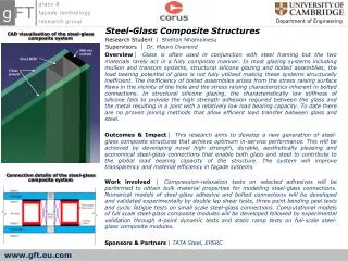
Traction Test Traction Test of a soft matrix fiber-reinforced Composite under tension: • 2 plies of initial angles +/- 50 degrees • Initial geometry of 2 in. x 0.01 in. • Length of the ends of the specimen do not change Traction Test Specimen Initial Finite Element Mesh Finite Element mesh at 30% Elongation
Traction Test Remarks: • The deformations must be monitored to prevent elongation of the fibers • The computation of the local fiber angle provides valuable information on the process Fiber angle at 30% elongation Finite Element mesh at 30% elongation
Tube Manufacturing Process Geometry Simulation of a Tube Manufacturing Process: • Cylindrical fiber weaves and mold of same diameter • The bases are fixed to coincide with each other Fiber Weaves: Cylinder of 5 in. diameter and 18 in. long Mold: Bent Cylinder of 5 in. diameter and radius of curvature of 11 in. Result: Fiber Weaves fitted over the mold
Summary • A non-traditional computational simulation method with a seamless computer code for non-linear structural response/behavior was described • It is bottoms-up synthesis; top-down decomposition with incremental linear updating • Its versatility was demonstrated by presenting simulating results from • Composite panel fracture • Composite burst • Composite containment • Composite pre-forms manufacturing • The method/computer code is unique • Only one of its kind