Download
1 / 27
270 likes | 855 Vues
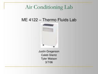
Air Conditioning Lab. ME 4122 – Thermo Fluids Lab Justin Gregerson Caleb Glantz Tyler Watson 3/7/06. Presentation Outline. 1.0 Lab Objective 2.0 Summary 3.0 Theory and Analysis 4.0 Equipment 5.0 Methods of Measurement 6.0 Procedure 7.0 Results and Discussion

E N D
Air Conditioning Lab ME 4122 – Thermo Fluids Lab Justin Gregerson Caleb Glantz Tyler Watson 3/7/06
Presentation Outline 1.0 Lab Objective 2.0 Summary 3.0 Theory and Analysis 4.0 Equipment 5.0 Methods of Measurement 6.0 Procedure 7.0 Results and Discussion 6.0 Conclusion and Recommendations 7.0 Questions?
Objective • The objective of this lab was to analyze the performance of an actual air conditioning unit based on experimental measurements.
Summary • The air conditioning unit was analyzed and the performance was evaluated. Based on the measured dry bulb temperatures and pressures, enthalpies and entropies were calculated for each state point. These values were used to calculate the Refrigeration Effect of 5283 BTU/hr, Coefficient of Performance of 2.304 and a Energy Efficiency Ratio (EER) of 7.865 BTU/W * hr. • For the air side analysis the dry bulb temperatures and relative humidity of the room, condenser outlet and evaporator outlet were used to calculate specific humidity, enthalpies and wet bulb temperatures. In conjunction with these calculated values the mass flow-rate of the air passing by the evaporator and condenser was used to determine the heat load rejected to the environment. The total heat load amounted to 6755 BTU/hr. • In order to achieve performance values closer to the manufactures rated performance the same conditions they used should be used for this lab. The ambient air temperature they used was 35°C and for these calculations the room temperature was 24.4°C. Since our temperature was lower there was less heat transfer to the R22 effectively decreasing our heat capacity and performance. The following report contains further analysis and complete results of the experiment performed.
Theory and Analysis • The air conditioning unit can be analyzed by breaking it down to resemble an ideal vapor-compression refrigeration cycle. • The processes involved in the cycle were: • Isentropic Compression from points 1-2 where it was assumed to be adiabatic. • Constant pressure heat transfer out of the system in the piping from points 2-3. • Adiabatic throttling process through the condenser from points 4-5 where the h values remained constant. • From points 5-6 there is a constant pressure heat transfer into the system through the evaporator.
Departures from the Ideal Cycle • There were some differences that the A.C unit had with respect to the ideal cycle so it became more reasonable to model it after the actual vapor-compression refrigeration cycle. • There were two systems that were evaluated, the air side which is an open system where mass can be transferred and the R22 coolant side which is a closed system that has no mass transfer
T-s Diagram • The evaporator outlet and the compressor inlet (points 1 and 6) • and the compressor outlet and the condenser inlet (points 2 and 3) • are too close to discern on a reasonably scaled chart.
Quality of Evaporator Inlet and COP • The above equation was used to solve for the enthalpy at point 5 due to the fact that is it a mixture with an unknown quality. Since the enthalpy at evaporator inlet and the condenser outlet are equal. The enthalpy of the saturated vapor and latent heat of vaporization are found from the tables that were provided for water vapor. The coefficient of performance is directly solved for using the answers found in Eqns. 8-10. This value is one of the rating factors for the air conditioning unit. Since the quality is now known from the enthalpy equation the entropy at point 5 can be calculated by using the above equation and the known values from the tables attached to the lab instructions.
Capacitance and EER The capacitance equation used the values found in Eqn. 10 and 8. The capacitance should be lower than the rated valued due to the lab conditions. The EER is COP times a constant ratio that gives the industry rating of the unit. The EER found in the lab was reasonably smaller than that provided by Panasonic.
Equipment • Haier Model # HPAC9M Portable Air Conditioner • Omega RH83 Digital Sling Psychrometer/Thermo Hygrometer • FLUKE 336 Clamp Meter (Ammeter) • Data Acquisition System described in the Instrumentation Lab Background • EXTECH Instruments Model No. 451112 Vane Anemometer • Control Company Model No. 14-648-51 Aneroid Barometer • Mitutoyo Model No. CD-6”CS Digital Caliper • Extech Multimaster 560 digital multimeter
Methods of Measurement • Six type K thermocouples are connected to the data acquisition system and mounted at key points in the refrigerant piping; the evaporator outlet, the compressor inlet, the compressor outlet, the condenser inlet, the condenser outlet, and the evaporator inlet. This placement was predetermined for this experiment and correlate to the points 1-6 in Figures 2 and 3. • Omega RH83 Digital Sling Psychrometer/Thermo Hygrometer was used to find the room dry-bulb temperature and the relative humidity of the air surrounding the unit by holding the unit anywhere that is reasonably far from the exit points of the unit. This device is also used to find the dry bulb temperature and relative humidity of the evaporator and the condenser outlet points by holding the psychrometer in front of the air flows leaving both outlets. • • FLUKE 336 Clamp Meter (Ammeter) was used to find the current flow into the compressor by clamping around the red wire that is easiest to access behind the control panel of the air conditioning unit. • • Extech Instruments Model No. 451112 Vane Anemometer used to measure the outlet velocity from the condenser and the evaporator. This device must be held with the yellow dot on the side with the air flow hitting it. • Control Company Model No. 14-648-51 Aneroid Barometer used for taking the pressure of the atmosphere in the room. Device is factory calibrated so the values can be read directly off of the device and used in calculations with an uncertainty of .05 kpa. • Mitutoyo Model No. CD-6”CS Digital Caliper measured the outlet areas of the condenser and evaporator air flows. Make sure that multiple measurements are taken of the inner diameters of the outlet ducts since they aren’t exactly circular. The uncertainty of this device can be neglected do to the multiple measurements and averaging done in finding the values. • Extech Multimaster 560 digital multimeter found the wall outlet voltage that the air conditioning unit was taking its power from. This is done by sticking the positive and negative probes into the wall socket and reading the value from the meter.
More Methods of Measurement • Two Bourdon tube pressure gauges are attached to the refrigerant piping at the evaporator outlet and the compressor outlet. The bourdon tubes were used to measure the evaporator and compressor outlet pressures of the R22 refrigerant. The pressure gauges can be read with two different scales, the psi scale was used with an uncertainty of .5psi. • All measurements were taken at least twice and the average was found to minimize the error in measurement going into the calculations. Constant pressure through the condenser and the evaporator allows the assumption of inlet and outlet pressures in the evaporator and condenser being equal valid. The air conditioner unit must be allowed to run until the displays are shown to be as close to steady state as possible.
Procedure • Visually inspected all components of AC unit • Plugged in and turned on AC unit • Used digital caliper to measure condenser and evaporator outlets • Monitored R22 temperature until steady-state was reached • Recorded following values for the air side while AC unit is at steady-state: Room Pressure, Dry Bulb Temp, Relative Humidity; Condenser Outlet Velocity, Dry Bulb Temp, Relative Humidity; Evaporator Outlet Velocity, Dry Bulb Temp, Relative Humidity;
Results and Discussion • Analysis of the data obtained in the lab is made possible with the state postulate. If two independent properties are known than everything may be determined off of the measured values [1]. Examining the state of the R-22 refrigerant the working fluid flowing through the system requires the temperature and pressure at certain positions. In conjunction with the R22 properties tables the enthalpy and entropy of the fluid may be determined by interpolation [1]. • At state point five, the evaporator inlet, the temperature and pressure are relatively low thus the enthalpy and entropy values are correspondingly low (Table 1). At this point the fluid is a saturated mixture with a quality of 23.5 % water vapor. As the fluid flows through the evaporator the difference between the low evaporator temperature and the higher room air temp allow for heat transfer to the refrigerant. This effectively increases the energy contained in the fluid shown by the increase in enthalpy at the evaporator exit represented by state point 6. The specific enthalpy of the refrigerant entering the evaporator is 97.25 kJ/kg, while the exiting is a much greater 250.75 kJ/kg.
As desired the R22 is now on the superheated region giving the fluid a higher quality so moisture doesn’t harm the compressor blades. State points one and two respectively represent the inlet and outlet conditions of the R22 over the compressor (Table 1). Over the compressor the pressure increases raising the temperature which also increases the specific enthalpy from 252.09 kJ/kg entering to 281.31 exiting the compressor. The idea is to raise the temperature going into the condenser as high as possible so more heat can be rejected to a heat sink. Increasing the high temp of rejection overall increases the efficiency of heat transfer or the coefficient of performance. • The condenser is the next component the R22 will travel through, corresponding to state points three and four. The goal is to reject heat from the R22 so more thermal energy may be absorbed when the fluid makes its way back down to the evaporator. This is represented by the decrease in temperature and enthalpy from state point three to four. Here the specific enthalpy decreases from 281.05 kJ/kg for the refrigerant entering the condenser to 97.25 for the refrigerant exiting the condenser.
Following the condenser are the capillary tubes, represented as state points four to five. Capillary tubes act as a throttling device which utilizes the Joule-Thompson Effect where a large drop in temperature is associated with a large drop in pressure from expansion [1]. Our capillary tubes are idealized assuming that it is an adiabatic throttling process. This allows the tubes to be viewed as an isenthalpic device where the enthalpy remains constant. This is an important assumption because it allows the enthalpy value obtained at the condenser exit to be used at the evaporator entrance. • Along with enthalpy the entropy of the system at different state points may also be interpolated using the temperature and pressure measurements obtained experimentally. The values of specific entropy noted as “s” may be viewed in the above Table 1. These values are used along with the dry-bulb temperatures to graphically represent the cycle (Fig 3).
Now the refrigeration effect or capacity may be determined by examining the change in specific enthalpy over the evaporator since this is the location of thermal energy addition. The calculated rate of heat transfer from the air to the refrigerant was 5.238*10^3 BTU/hr. This is lower than the 8,000 BTU/hr rated performance of the air conditioner because the room air temperature used in the experiment was 24.4 °C, which is lower than the room air temp of 35 °C used by Panasonic Industrial Company [4]. Since the difference of air temp and R22 temp entering the evaporator found experimentally was lower than the temperature difference the manufacturer used there will be less heat transferred to the refrigerant. The general rule is that the greater the temperature difference the greater the heat transfer. • The “efficiency” of the refrigerator was determined by Coefficient Of Performance (COP) and the Energy Efficiency Ratio (EER). The COP calculated was 2.304 and the EER was 7.865 BTU/W*hr. This is also lower than the manufacturer’s rated performance of EER which is 10.75 BTU/W*hr for the same reason that the refrigerating capacity was lower, the same testing conditions were not used to evaluate the system.
Another part of the analysis was to determine the states of the air entering the AC or the room’s air and air exiting through either the evaporator or condenser. This encompasses using the relative humidity and dry bulb temperatures measured during the experiment to determine the wet-bulb temp, specific humidity, and the specific enthalpy of the air and water vapor mixture (Table 2). The incoming air temp is greater than the air temp exiting the evaporator since thermal energy is extracted from the air by the refrigerant shown by the decrease of specific enthalpy. This is the desired effect of an air conditioner, take air from the room, cool it off and return it into the room. Over the evaporator and condenser moisture is removed from the incoming air, represented by the decreases in specific humidity. • Water condenses out of the room air on the cold evaporator coils thus decreasing the ratio of mass of water vapor to mass of dry air. This is a cooling and dehumidifying process. The increased air temp leaving the condenser is to the thermal rejection of heat since the condenser coil temperature is greater than the surrounding room air temp. The enthalpy of the air also increases relative to the increase in air temp. The relative humidity values measured increase and decrease according to the air temp and the actual amount of moisture present in the air. When the air temp and moisture content exiting decreases such as over the evaporator the relative humidity will increase since the air is less able to contain moisture. While the opposite occurs over the condenser and the relative humidity decreases. The wet-bulb temperatures were estimated by examining a psychrometric chart. These values are supplemental and not actually used for calculation purposes.
The heat rejected to the surroundings may be obtained by using the values of specific enthalpy obtained along with the mass flow-rate of air going across the evaporator and the condenser. The rate of heat load from the room air entering to the room air exiting the evaporator is -5,291 BTU/hr. The negative sign convention accounts for energy being taken out of the air. This value is greater than the heat capacity taken in by the refrigerant because the energy transfer for the air accounts for the energy taken out by the refrigerant in addition to the latent heat of vaporization released by the condensing water over the evaporator. The heat load of the air entering and exiting the condenser is 6,755 BTU/hr. So the overall heat load rejected is the sum of the two amounting to 1,465 BTU/hr. In this experiment the heat is being added back into the room since the condenser isn’t placed outside.
Conclusions and Recommendations • All of the data collected during this experiment is enough to explain to any engineer or layman what the air conditioning unit will do when it is put into use in the lab settings. Anyone can use the same type of system to analyze any air conditioning unit to see what the actual output of the unit into the surrounding environment will be instead of going by what the optimum values are that are provided by the manufacturer that are purposely skewed to make their product seem better. • The pros of doing the lab this way was that it can be performed by anyone as long as supporting instructions and directions are given in a clear manner. It is simplified to a point where the valuable information emerges. Simplifying a system allows the important areas to be evaluated with less stress on obtaining the so called “right” answer. The bad part of making these simplifying assumptions are that certain error in the calculations are introduced making the values mere estimates. For the purpose of this lab which was to analyze the performance of an air conditioning system based on measurements, these certain assumptions were all simplifications that proved to be beneficial.
Conclusion and Recommendations • In order to get this lab to be more effective it should be in a controlled environment. The air conditioning unit should be placed in a room with a temperature like the rated temp and as close to ideal air conditions as possible. Also limiting the uncertainty in the measurement devices would decrease the difference in the known values and the found values for the unit. The measurements were taken in the positions that would account for the right amount of heat load and enthalpy for each state that the flow goes through. Simplifying assumptions were made during the experiment to make the data easier to collect and analyze. The effects of the pressure loss could be analyzed but should be small enough to where there would be no significant difference in the values reached. • After a complete analysis was performed the original hypothesis pertaining to the heat capacity and EER provided by Panasonic being greater than the values we obtained experimentally was accepted. It was assumed that the heat capacity for our lab settings was going to be lower then the manufacturer’s since the temperature in our lab was lower than the ambient air temperature they used minimizing the heat transfer from the air to the refrigerant. Through measurements we obtained a heat capacity of 5,238 BTU/hr compared to the claimed 8,000 BTU/hr put out by Panasonic, which shows that a significant amount of thermal energy is still being absorbed by the refrigerant over the evaporator. • Since the COP and the EER are directly related to the heat capacity and the work going into the compressor to transfer heat from a low temperature region to a high temperature, the values obtained experimentally will also be lower than the ones claimed. Experimentally the COP was found to be 2.304 and the EER was 7.865 compared to Panasonics COP of 3.145 and EER of 10.75 BTU/W/hr. The lab effectively demonstrated how an air conditioner functioned and how certain efficiencies are determined.