Electric Current, Potential Difference and resistance
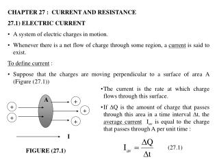
Electric Current, Potential Difference and resistance. Electric Current. Means “flow of charge” Refers to quantity of charge that passes a single point in time. SI unit of current is the ampere (A) which is equivalent to 1 coulomb per second I = Δ q / t. Example.

Electric Current, Potential Difference and resistance
E N D
Presentation Transcript
Electric Current • Means “flow of charge” • Refers to quantity of charge that passes a single point in time. • SI unit of current is the ampere (A) which is equivalent to 1 coulomb per second I = Δq / t
Example • What is the electric current in a conductor if 240 C of charge pass through it in 1.0 min. Remember - Time must be measured in seconds I = Δq / t = 240 C / 60. s = 4.0 A • In metallic conductors, the current is carried by freely moving electrons; in solutions, the current is carried by ions; in gases, the current is carried by both electrons and ions.
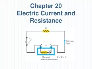
Current and Potential Difference • To initiate the flow of charge, potential difference is necessary: Flow of positive charges --------- _ + -----------Flow of electrons V
Conventional current • Potential difference is oriented so that positive charges will flow toward the right (negative terminal) while negative charges (including electrons) will move towards the left (the positive terminal) • The flow of positive charges is conventional current and its direction is always opposite to the direction of electron flow (the magnitude is the same)
Resistance • “Electrical analog of friction” • Defined as the ratio of potential difference to current R = V / I • SI unit of resistance is the volt per ampere (V/A), which is called the ohm (Ω) in honor of German physicist Georg Ohm.
Example • When a conductor has a potential difference of 110 V placed across it, the current through it is 0.50 A. What is the resistance of the conductor? Solution: R = V / I = 110 V / 0.50 A = 220 Ω
Resistance and Resistivity Resistance of a material depends on • The nature of the material • The geometry of the conductor And • The temperature at which the resistance is measured.
Metallic substances are good conductors • they have low resistances. • Silver and Copper are the best metallic conductors. • Resistivity (ρ) measures how well a substance resists carrying current • Unit is the ohm•meter (Ω•m) • Resistivity table is on reference table http://www.emsc.nysed.gov/osa/reftable/physics-rt/physics06tbl.pdf
Resistance of a regularly shaped conductor is directly proportional to its length and inversely proportional to its cross – sectional area. • Logical – longer conductors increase likelihood that electron will collide with the atoms of conductor – increasing resistance. • Making conductor wider increases number of possible electron paths – decreasing resistance.
Resistance of metallic conductor increases with rising temperature • Increases vibrational kinetic energy of its atoms, making collisions with electrons more likely. • In Semiconductors, resistance decreases with rising temp. • 20° C is chosen as a standard temperature for comparing resistances
Combining all of these factors: R = ρ ∙ L/A (at a specified temperature) Where L represents the length of the conductor an A is its cross – sectional area.
example Calculate the resistance at 20° C of an aluminum wire that is 0.200 meter long and has a cross – sectional area of 1.00 x 10⁻³ sq. meter. Solution: From resistivity table – Aluminum has a resistivity of 2.82 x 10⁻⁸Ω∙m R = ρ ∙ L/A = 2.82 x 10⁻⁸Ω∙m (0.200 m)/ (1.00 x 10⁻³ m2) = 5.64 x 10 -6 Ω
homework • Read pg 120-123 • Do pgs 124-125 #29 - 48
Ohm’s Law V = I R I R _ + V
Ohm’s Law: V = IR • A fundamental relationship in electric circuits. • Describes how much potential difference is required to move charges through a resistance at a given current. • Materials that have constant resistances are said to obey Ohm’s Law
Power and Energy in Electric Circuits • Rate at which energy is supplied to a circuit is Power P = VI measured in Watts Can also be stated as: P = VI = (IR) I = I2R or P = VI = V (V/R) = V2/R
EXAMPLES • Calculate the rate at which energy is supplied by a 120 V source to a circuit if the current in the circuit is 5.5 A Solution: P=VI = (120V)(5.5 A) = 660 W 2) A 150 Ω resistor carries a current of 2.0 A. Calculate the rate at which heat energy is produced in resistor Solution: Pheat = I2R = (2.0 A)2(150 Ω) = 600 W
Energy (W) • Recall: Power = Work / time Therefore Work (energy) = Power x time W = Pt = VIt = I2RT = V2t / R Unit is joules
Example • How much energy is produced by a 50 V source that generates a current of 5.0 A for 2 minutes? Solution: Don’t forget time must be in seconds! W = VIt = (50 V)(5.0 A)(120 s) = 30,000 J = 30 kJ
Series Circuits Or why old Christmas lights used to all go out when only one bulb was broken
Series Circuit • Has only one current path and if that path is interrupted, the entire circuit ceases to operate.
The diagram represents a circuit containing three resistors in series with meters placed to measure various characteristics of the circuit • - A - represents an ammeter, a very low resistance device that measures current in a circuit. • - V - represents a voltmeter, a very high resistance device that measures potential difference across a circuit
In Series circuits… • Current throughout the circuit is constant; therefore ammeter can be placed at any position. • Potential Difference is equal to the SUM of the potential differences across all resistances • Known as Kirchhoff’s first rule (or simply the loop rule) • Ohm’s law holds for each resistance
For series circuits • I = I1 = I2 = I3 = … • V = V1 + V2 + V3 + … • Req = R1 + R2 + R3 + … - this is the equivalent resistance of the circuit
Example – calculate the meter readings 24 V Vt 3Ω 6Ω 9Ω
Solution • First find equivalent resistance Req = R1 + R2 + R3 + … = 3Ω + 6Ω + 9Ω = 18Ω • The total potential difference, VT = 24 V since the source supplies the entire circuit • The current through circuit (I) is V=I Req 24 V = I (18Ω) I = 1.33 A
Solution cont’d • Potential difference across each resistance can be found using Ohm’s Law V=IR V1 = (1.33 A) (3Ω) = 4 V V2 = (1.33 A) (6Ω) = 8 V V3 = (1.33 A) (9Ω) = 12 V
Important Fact! • As the number of resistances in a series circuit increases, the equivalent resistance, of the circuit increases and the current through the circuit decreases.
Example • Suppose a fourth resistance of 18Ω is added to the series circuit. Calculate (a) equivalent resistance of circuit Req = R1 + R2 + R3 + … = 3Ω + 6Ω + 9Ω + 18Ω = 36Ω (b) the current through the circuit V=I Req 24 V = I (36Ω) I = 0.67 A
Parallel Circuits • Have more than one current path. • If a segment of a // circuit is interrupted, the result will not necessarily be that the entire circuit ceases to operate. • House wiring is in //.
Parallel circuits • Current separates into more than one path. • The point where separation occurs is known as ajunction • The sum of the currents entering a junction must equal the sum of the currents leaving the junction • This is Kirchoff’s second rule (or simply the junction rule)
example • In the diagram below, what are the magnitude and the direction of the current in wire X? 1A X 2A 4A
For any // circuit • V = V1 = V2 = V3 = … = Vnvoltage is constant • I = I1 + I2 + I3 + … + In current through entire circuit is equal to the sum of the currents through all resistances (Kirchoff’s 2nd rule) • Vn = InRn
example • Calculate (a) the equivalent resistance (b) Currents I1 and I2 (c) Total current of the following circuit. I1 3 Ω I2 6 Ω IT 24 V
Solution a) To find equivalent resistance:
Solution (cont’d) b) To find I1 and I2 and c) IT I1 3 Ω I2 6 Ω IT 24 V
Important Note • The equivalent resistance is less than any single resistance in the circuit. • If more resistance is added in //, the equivalent resistance decreasesand the total current increases. • The result is roughly equivalent to increasing the cross-sectional area of a conductor. • This is why overloading a household circuit by connecting too many electrical appliances is dangerous. • As current increases, the amount of heat energy also increases. This can lead to fires • Fuses and circuit breakers are designed to prevent such fires from occurring.
example • A 2 – ohm resistor is added in parallel to the previous circuit. Calculate (a) the equivalent resistance and (b) the total current of the altered circuit. I(2Ω) 2 Ω I1 3 Ω I2 6 Ω IT 24 V