Data Conversion Methods
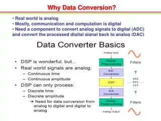
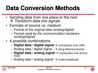
Data Conversion Methods. Sending data from one place to the next Transform data into signals Formats of source vs. medium Format of the original data (analog/digital) Format used by the communication hardware (analog/digital) 4 possible combinations

Data Conversion Methods
E N D
Presentation Transcript
Data Conversion Methods • Sending data from one place to the next Transform data into signals • Formats of source vs. medium • Format of the original data (analog/digital) • Format used by the communication hardware (analog/digital) • 4 possible combinations • Digital data / digital signal (computers over LAN) • Analog data / digital signal (long distance phone) • Digital data / analog signal (computers over phone lines) • Analog data / analog signal (radio broadcast) ECE 766 Computer Interfacing and Protocols
Baseband Digitally Encoded Resources shared by Time Division Multiplexing Broadband Analog Modulation Resources shared by Frequency Division Multiplexing Frequency Time PSTN Data Encoding / Modulation Should I have called the vertical axis bandwidth? ECE 766 Computer Interfacing and Protocols
Terminology • Data rate (bps) • Baud rate, “modulation rate” (signal elements/sec) • Mark (1) and space (0) conditions(from telegraphy) • Connection types • Simplex: One way • Half Duplex: Two way, but only one way at a time • (Full) Duplex: Two way simultaneously ECE 766 Computer Interfacing and Protocols
Criteria for a Good Encoding Scheme • Signal Spectrum • Minimize high frequency components • No DC components • Synch capability (find bit positions) • Signal error detection capability • Signal interference and noise immunity • Cost and complexity ECE 766 Computer Interfacing and Protocols
Absolute vs. Differential Encoding / Modulation Schemes • Absolute: • Each signal corresponds to a predetermined information unit • The meaning of a signal sequence is fixed, not relative. • Differential: • Information is encoded by difference between current and previous signal element • The meaning of a signal sequence is relative, not absolute. ECE 766 Computer Interfacing and Protocols
Digital Encoding Schemes • Digital information is converted to a sequence of voltage pulses that propagate over the link • Three subcategories by voltage use: • Unipolar (Zero and Positive) • Polar (Negative and Positive) • Bipolar (Negative, Zero, and Positive) ECE 766 Computer Interfacing and Protocols
Amplitude 1 0 1 1 1 0 0 0 Time Unipolar Encoding • Uses zero and positive voltage pulses to encode binary data • Not really “encoded” at all! ECE 766 Computer Interfacing and Protocols
Polar Encoding • Polar encoding uses a positive and a negative voltage level to represent bits Solves the DC component problem(if balanced) • Categories: • Nonreturn to Zero (NRZ) • NRZ-L (L=Level) • NRZ-I (I=Inverted) • Return to Zero (RZ)(as shown in book) • Biphase • Manchester • Differential Manchester ECE 766 Computer Interfacing and Protocols
1 0 1 1 1 0 0 0 Amplitude Time Nonreturn to Zero (NRZ) • The voltage level is constant during a bit interval, i.e., no returns to zero • Absolute and differential versions • Absolute NRZ: NRZ-L (L=Level)(like ntl) • 0 = Positive voltage • 1 = Negative voltage ECE 766 Computer Interfacing and Protocols
1 0 1 1 1 0 0 0 Amplitude Time Nonreturn to Zero (NRZ) • Differential NRZ: NRZ-I (I=Inverted) • A bit is represented by the transition of the voltage level, not the voltage level itself! • 0 = No inversion at beginning of bit interval • 1 = Inversion at beginning of bit interval ECE 766 Computer Interfacing and Protocols
Nonreturn to Zero (NRZ) • Evaluation • No DC component • Simple • Few high frequency components • Synchronization • No synchronization at large (consider a string of the same bit) • NRZ-I provides synchronization for every 1 encountered can handle strings of 1s(superior to NRZ-L) ECE 766 Computer Interfacing and Protocols
1 0 1 1 1 0 0 0 Amplitude Time Return to Zero (RZ)(bipolar form) • Targets to solve the synchronization problem • A scheme that handles both strings of both 1s and 0s • Voltage level change for every bit value three levels: +,-, 0 • 0 = Transition from negative to zero • 1 = Transition from positive to zero ECE 766 Computer Interfacing and Protocols
Return to Zero (RZ) • Variations used also for magnetic recording (no synchronization capability) • Evaluation • Solves synchronization problem • Two signal changes / bit More transitions Occupies more bandwidth ECE 766 Computer Interfacing and Protocols
1 0 1 1 1 0 0 0 Amplitude Time Biphase • Signal changes in the middle of the bit interval, but does not return to zero • Signal change bit representation synchronization • Manchester: • 0 = Transition from positive to negative • 1 = Transition from negative to positive ECE 766 Computer Interfacing and Protocols
1 0 1 1 1 0 0 0 Amplitude Time Biphase • Differential Manchester: • 0 = Transition at the beginning of bit period • 1 = No transition at the beginning of bit period • Evaluation: • Not as simple • Higher frequency components (as RZ) • Synchronization capability • No DC component ECE 766 Computer Interfacing and Protocols
Bipolar • Like in RZ, three voltage levels are used • Zero voltage level used for binary 0 • Categories: • Alternate Mark Inversion (AMI) • Bipolar 8-Zero Substitution (B8ZS) North America • High Density Bipolar 3 (HDB3) Europe and Japan ECE 766 Computer Interfacing and Protocols
1 0 1 1 1 0 0 0 Amplitude Time Alternate Mark Inversion (AMI) • Uses three voltage levels • 0 = Zero volts • 1 = Non-zero voltage, opposite in polarity to the last logical 1 • Evaluation • No DC component • Synchronized only for 1s, not 0s • Error detection ECE 766 Computer Interfacing and Protocols
0 0 0 0 0 0 0 1 0 0 1 Amplitude Time Violation Violation Bipolar 8-Zero Substitution (B8ZS) • Adds synchronization for long strings of 0s • North American system • Same working principle as AMI except for eight consecutive 0s • Evaluation • Adds synchronization without changing the DC balance • Error detection possible 10000000001 +000+-0-+01 in general00000000000V(-V)0(-V)V ECE 766 Computer Interfacing and Protocols
High Density Bipolar 3 (HDB3) • Goal like B8ZS to improve Sync of AMI • Just like AMI except 4 0’s are replaced by code • For 0000 use 000V or B00V • Where B and V are + or – • And V is AMI violation, B is Balance Bit • Use 000V if EVEN number of + and – pulses so far • Use B00V if ODD, and B is opposite last pulse ECE 766 Computer Interfacing and Protocols
High Density Bipolar 3 (HDB3) • Same goal as B8ZS • Based on AMI • Replaces every four consecutive 0s based on • Number of pulses since last substitution • Polarity of last logical 1 ECE 766 Computer Interfacing and Protocols
High Density Bipolar 3 (HDB3) • Example: (revised 1-13-06) • Number of 1s since last substitution is even, last 1 negative (before this string) • Encode 100000000001 0 0 0 0 0 0 0 1 1 0 0 0 Amplitude Time ECE 766 Computer Interfacing and Protocols