Data Conversion Fundamentals
Data Conversion Fundamentals. Analog-Digital Converters Online Seminar Fall 2002. The World Leader in High-Performance Signal Processing Solutions. Introduction to A/D Converters. A/D Converter (ADC) Introduction. A/D Fundamentals Sampling Quantization

Data Conversion Fundamentals
E N D
Presentation Transcript
Data Conversion Fundamentals Analog-Digital Converters Online Seminar Fall 2002
The World Leader in High-Performance Signal Processing Solutions Introduction to A/D Converters
A/D Converter (ADC) Introduction • A/D Fundamentals • Sampling • Quantization • Factors Affecting A/D Converter Performance • Static Performance • Dynamic Performance • ADC Architectures • SAR ADCs • Pipelined ADCs • Flash Type ADC • Sigma-Delta ADCs • High Speed ADC Application Considerations
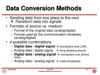
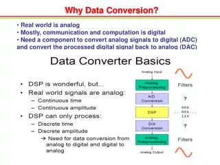
n bits ANALOG SIGNAL PROCESSOR A - D CONVERTER MUX • Operational Amp • Differential Amp • Instrumentation Amp • Isolation Amp • Multiplier/Divider • Log Amplifier • rms-dc Converter • F-V/V-F Converter MICRO PROCESSOR OR DSP PROCESSOR REFERENCE ANALOG SIGNAL PROCESSOR D - A CONVERTER MUX n bits The Measurement & Control Loop
“REAL WORLD” SAMPLED DATA SYSTEMS CONSIST OF ADCs and DACs ADC SAMPLED AND QUANTIZED WAVEFORM DAC RECONSTRUCTED WAVEFORM
REFERENCE INPUT RESOLUTION N BITS DIGITAL OUTPUT ANALOG INPUT Analog Input DIGITAL OUTPUT CODE = x (2N - 1) Reference Input What is an Analog-Digital Converter? • Produces a Digital Output Corresponding to the Value of the Signal Applied to Its Input Relative to a Reference Voltage • Finite Number of Discrete Values : 2NResulting in Quantization Uncertainty • Changes Continuous Time Signal into Discrete Time Sampled Representation • Sampling and Quantization Impose Fundamental yet Predictable Limitations
Sampling Process • Representing a continuous time domain signal at discrete and uniform time intervals • Determines maximum bandwidth of sampled (ADC) or reconstructed (DAC) signal (Nyquist Criteria) • Frequency Domain- “Aliasing” for an ADC and “Images” for a DAC
Quantization Process • Quantization Process • Representing an analog signal having infinite resolution with a digital word having finite resolution • Determines Maximum Achievable Dynamic Range • Results in Quantization Error/Noise Any Analog Input in this Range Gives the Same Digital Output Code
111 110 101 DIGITAL OUTPUT 100 1 LSB 011 010 001 1/8 2/8 3/8 4/8 5/8 6/8 7/8 ANALOG INPUT Conversion Relationshipfor an Ideal A/D Converter
111 110 101 DIGITAL OUTPUT 100 011 010 001 1/8 3/8 4/8 5/8 6/8 7/8 FS 2/8 NORMALIZED ANALOG INPUT quantization noise error Quantization Noise q = 1 LSB
+q/2 0 volts -q/2 Quantization Noise (con’t) • The RMS value of the quantization noise sawtooth is its peak value, q¸2, divided by Ö 3, or q ¸ Ö12 • For Sine Wave Full Scale RMS Value is 2(N-1)/Ö2 • For Saw Tooth Quantization Error Signal RMS Value is q /Ö12 • Thus S/N is 1.225 x 2N • Expressed in dB as 1.76 + 6.02N, where N is the resolution of the A/D converter
Quantization Noise (con’t) HARMONICS OF FSIGNAL (EXAGGERATED FOR CLARITY) OUTPUT RMS QUANTIZATION NOISE FS/2 FS FSIGNAL • If the quantization noise is uncorrelated with the frequency of the AC input signal,the noise will be spread evenly over the Nyquist bandwidth of Fs/2. • If, however the input signal is locked to a sub-multiple of the sampling frequency, the quantization noise will no longer appear uniform, but as harmonics of the fundamental frequency
Unipolarand Bipolar Converter Codes FS - 1LSB FS - 1LSB FS - 1LSB 0 0 0 ALL ALL "1"s "1"s 1 AND ALL "0"S -(FS - 1LSB) -FS OFFSET BINARY 2’s COMPLEMENT UNIPOLAR
Factors AffectingA/DConverterPerformance- Offset And Gain for Unipolar Ranges ACTUAL ACTUAL GAIN ERROR IDEAL IDEAL ZERO ERROR WITH GAIN ERROR: OFFSET NO GAIN ERROR: OFFSET ERROR = 0 ZERO ERROR = OFFSET ERROR 0 0
Factors AffectingA/DConverterPerformance- Offset And Gain for Bipolar Ranges ACTUAL ACTUAL IDEAL IDEAL 0 0 ZERO ERROR ZERO ERROR OFFSET WITH GAIN ERROR: NO GAIN ERROR: OFFSET ERROR = 0 ZERO ERROR = OFFSET ERROR ERROR ZERO ERROR RESULTS FROM GAIN ERROR
DC Specifications (Ideal) • Ideal ADC code transitions are exactly 1 LSB apart. • For an N-bit ADC, there are 2N codes. (1LSB = FS/ 2N ) • For this 3-bit ADC, 1 LSB = (1V/23 = 1/8th) • Each “step” is centered on an eighth of full scale
DC Specifications (DNL) • Differential Non-Linearity (DNL) is the deviation of an actual code width from the ideal1 LSB code width • Results in narrow or wider code widths than ideal and can result in missing codes • Results in additive noise/spurs beyond the effects of quantization
DC Specifications (DNL) • DNL error is measured in lsbs. • A given ADC will have a typical DNL pattern. • These patterns will also have an element of randomness to them.
DC Specifications (INL) • Integral Non-Linearity (INL) is the deviation of an actual code transition point from its ideal position on a straight line drawn between the end points of the transfer function. • INL is calculated after offset and gain errors are removed • Results in additive harmonics and spurs
DC Specifications (INL) • Some typical INL patterns Bow indicates 2nd order nonlinearity “S” indicates 3rd order nonlinearity
QUANTIFYING ADC DYNAMIC (AC) PERFORMANCE • Harmonic Distortion • Worst Harmonic • Total Harmonic Distortion (THD) • Total Harmonic Distortion Plus Noise (THD + N) • Signal-to-Noise-and-Distortion Ratio (SINAD, or S/N +D) • Effective Number of Bits (ENOB) • Signal-to-Noise Ratio (SNR) • Analog Bandwidth (Full-Power, Small-Signal) • Spurious Free Dynamic Range (SFDR) • Two-Tone Intermodulation Distortion • Noise Power Ratio (NPR) or Multitone Power Ratio (MPR)
POWER SUPPLIES LOW PHASE JITTER SAMPLING CLOCK SOURCE A/D CONVERTER ON EVALUATION BOARD BANDPASS FILTER FFT ANALYZER LOW PHASE JITTER SINEWAVE SOURCE Dynamic Testing of A/D Converters • A Fast Fourier Transform (FFT) Analyzer is used to measure dynamic performance
amplitude amplitude 2f1 3f1 f1 time frequency Fast Fourier Transform converts this… f1 2f1 3f1 ...to this
0 dB SNR = 6.02N + 1.76 dB 18 dB, M = 128 21 dB, M = 256 24 dB, M = 512 27 dB, M = 1024 30 dB, M = 2048 33 dB, M = 4096 RMS Quantization Noise Level FFT Floor = 10 log 10 (M ¸ 2) Bin Spacing = D F = FS¸ M An M-Point FFT The Effective Noise Floor of an M-Point FFT Is Less Than The RMS Value of the Quantization Noise
Nyquist Bandwidth & Aliasing • 2 Signals that are Mixed Together Produce Sum and Difference Frequency Components • Nyquist Theory Stipulates that the Signal Frequency, FSIGNAL must be < to ½ FSAMPLING to Prevent a Condition Known As “Aliasing”, in which the Difference Component Appears Within the Signal Bandwidth of Interest
fsampling - fsignal fsampling + fsignal fsignal fsampling signal passband 3 MHz 4 MHz 5 MHz 1 MHz The Nyquist Bandwidth & Aliasing(FSIGNAL< ½ FSAMPLING) The Signal Frequency Is < 1/2 the Sampling Frequency and So the Sum and Difference Components Fall Outside (Beyond) the Signal Passband
fsampling- fsignal fsampling + fsignal fsignal fsampling 1 MHz 1.5 MHz 2.5 MHz “Alias” 0.5 MHz The Nyquist Bandwidth & Aliasing(FSIGNAL> ½ FSAMPLING) The Signal Frequency Is > 1/2 (approx 2/3) the Sampling Frequency. An “Alias” or False Image is Thus Created that Falls Within the Passband of Interest.
SINAD, ENOB, and SNR • SINAD (Signal-to-Noise-and-Distortion Ratio) • The ratio of the rms signal amplitude to the mean value of the root-sum-squares (RSS) of all other spectral components, including harmonics, but excluding dc • ENOB (Effective Number of Bits) • SNR (Signal-to-Noise Ratio, or Signal-to-Noise Ratio Without Harmonics) • The ratio of the rms signal amplitude to the mean value of the root-sum-squares (RSS) of all other spectral components, excluding the first five harmonics and dc
ADC LARGE SIGNAL (OR FULL POWER) BANDWIDTH • Full-power bandwidth is defined as the input frequency where the fundamental in an FFT of the output, rolls off to its 3 dB point • ADC’s SHA generally determines the FPBW • FPBW often limited by slew rate of the internal circuitry. • May not be compatible with the converter’s maximum operating rate • Ideally fFPBW >> fs / 2 • Many High Speed Converters have fFPBW < fs / 2 • Use as a “prerequisite” specification for comparing ADC’s IF undersampling capabilities. But need to consider distortion as well.
“Recursive” One-Bit Sub-Ranging Architecture Successive Approximation ADC
How a Successive Approximation A/D Converter Works • Rising/Falling Edge of Convert Start Pulse Resets Logic • Falling/Rising Edge Begins Conversion Process • Bit Comparisons Made on Each Clock Edge • Conversion Time Equals Number of Comparisons (Resolution) Times Clock Period • The Accuracy of Conversion Depends on the DAC Linearity and Comparator Noise
MSB 5.000V 2SB 2.500V 3SB 1.250V LSB 0.625V VIN > 5.000V VIN > 7.500V VIN > 6.250V VIN > 6.875V YES NO YES NO 0 1 0 1 How Successive Approximation Works EXAMPLE : ANALOG INPUT = 6.428V, REFERENCE = 10.000V
Successive Approximation ADC Advantages to SAR A/D converters • Low Power (12-bit/1.5 MSPS ADC: 1.7 mW) • Higher resolutions (16-bit/1 MSPS) • Small Die Area and Low Cost • No pipeline delay Tradeoffs to SAR A/D converters • Lower sampling rates • Typical Applications • Instrumentation • Industrial control • Data acquisition
Pipelined Sub-ranging ADC Conversion divided into discrete stages thus causing pipeline delay • 1st Stage ADC is 6-bit FLASH • 2nd Stage ADC is 7-bit Flash • Total resolution is 12 bits (one bit used for error correction)
Pipelined Sub-ranging ADC Advantages to Pipelined Sub-ranging A/D converters • Higher resolutions at high-speeds (14-bits/105 MSPS) • Digitize wideband inputs • Tradeoffs to pipelined sub-ranging A/D converters • Higher power dissipation • Larger die size Typical Applications • Communications • Medical imaging • Radar
Flash or Parallel ADC 2N-1 comparators form the digitizer array, where N is the ADC resolution Analog input is applied to one side of the comparator array, a 1 lsb reference ladder voltage is applied to the other inputs. The comparator array is clocked simultaneously and decides in parallel. Output logic converts from thermometer code to binary
Flash or Parallel ADC • Advantages to Flash A/D converters • Fastest conversion times (up to 1 GSPS) • Low data latency • Tradeoffs to Flash A/D converters • Higher power consumption • High capacitive input is difficult to drive • Typical Applications • Video digitization • High-speed data acquisition
FIRST-ORDER SIGMA-DELTA ADC CLOCK Kfs fs INTEGRATOR VIN ò DIGITAL FILTER AND DECIMATOR å A + N-BITS + _ _ fs LATCHED COMPARATOR (1-BIT ADC) B +VREF 1-BIT, Kfs 1-BIT DATA STREAM 1-BIT DAC –VREF SIGMA-DELTA MODULATOR
fs 2 Oversampling + Digital Filter + Decimation B Kfs fs DIGITAL FILTER ADC DIGITAL FILTER DEC REMOVED NOISE fs 2 Kfs 2 Kfs Oversampling + Noise Shaping + Digital Filter + Decimation C Kfs fs REMOVED NOISE SD MOD DIGITAL FILTER DEC fs 2 Kfs Kfs 2 OVERSAMPLING, DIGITAL FILTERING, NOISE SHAPING, AND DECIMATION fs QUANTIZATION NOISE = q / 12 q = 1 LSB A Nyquist Operation ADC fs
NOISE-FREE CODE RESOLUTION FULLSCALE RANGE P-P NOISE = log2 BITS 20mV FULLSCALE RANGE 6.6 × RMS NOISE NOISE-FREE CODE RESOLUTION log2 BITS = 0.4uVrms 16.5bits DEFINITION OF "NOISE-FREE" CODE RESOLUTION FULLSCALE RANGE RMS NOISE EFFECTIVE RESOLUTION = log2 BITS P-P NOISE = 6.6 × RMS NOISE = EFFECTIVE RESOLUTION – 2.72 BITS
SIGMA-DELTA ADCs Advantages to Sigma-Delta A/D converters • High resolutions and accuracy (24-bits) • Excellent DNL and INL performance • Noise shaping capability Tradeoffs in Sigma-Delta A/D converters • Limited input bandwidth • Slower sampling rates Typical Applications • Precision data acquisition and measurement • Medical instrumentation
High Speed ADC Time Domain Specifications Considerations • Aperture Jitter and Delay • ADC Pipeline Delay • Duty Cycle Sensitivity • DNL Effects
EFFECTS OF APERTURE AND SAMPLING CLOCK JITTER • Jitter: • Most systems assume the signal is sampled uniformly • Clock noise leads to non-uniform sampling (i.e. jitter) • Jitter leads to SNR degradation for high frequency inputs:
EFFECTIVE APERTURE DELAY TIME • Typically not an issue in frequency domain applications • May vary slightly among devices of same product due to variations in SHA bandwidth and CLK prop. delays