Download
1 / 41
410 likes | 560 Vues
This presentation by Eric Blumenstein, PE, from Golder Associates Inc., focuses on an innovative bench-scale passive treatment system designed for removing sulfate from mining-influenced water near an underground coal mine on Vancouver Island, BC. It discusses traditional sulfate removal technologies, explores biological sulfate removal options, and presents bench testing results. The study highlights considerations for demonstration system design to ensure low long-term operating costs and adaptability to the site's environmental conditions.

E N D
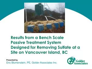
Results from a Bench Scale • Passive Treatment System • Designed for Removing Sulfate at a Site on Vancouver Island, BC Presented by, Eric Blumenstein, PE, Golder Associates Inc.
Presentation Overview • Site Location / Background • Desires / Needs of Site • Traditional Sulfate Removal Technologies • Biological Sulfate Removal • Bench Testing Construction (March 2011) • Bench Testing Results (Summer 2011) • Consideration for Demonstration System Design • Demonstration System Design Overview • Path Forward
Site Location / Background / Needs • Underground coal mine (not hard rock) • Active workings • Inactive workings • Seep into freshwater lake • Mining influenced water: • Sulfate • Iron • Arsenic • Desire for: • Low long-term operating and maintenance costs • Operate in cool weather • Fit on available land
Traditional Sulfate Removal Technologies • Reverse Osmosis (RO) Membrane Filtration: • Proven technology • Capital cost • Operating and maintenance cost • Labor • Chemicals • Power • Equipment maintenance • Brine production / disposal
Traditional Sulfate Removal Technologies • Chemical Precipitation • Barium chloride • Lime • Proven technology • Capital cost • Operating and maintenance cost • Labor • Chemicals • Power • Equipment maintenance • Sludge production / disposal
Potential New Sulfate Removal Technology • Biological sulfate removal: • Active or passive • Not a new concept • Biochemical reactors (BCR): • Sulfate reducing bioreactors (SRBR) • Succesive alkalinity producing systems (SAPS) • Reducing alkalinity producing sytsems (RAPS) • Limitations: • Sulfate reduction is limited by carbon availability • Need to sequester reduced sulfate
Potential New Sulfate Removal Technology • Sulfate biologically reduced to sulfide: • Some sulfide forms metal precipitates (metal sulfides) • Some adsorbs to surface area on substrate • Some sulfide leaves the BCR as sulfide anion or hydrogen sulfide • Excess sulfide in BCR effluent can: • Cause health and safety issue and • Convert back to sulfate upon leaving cell and being re-oxidized • Brock Biology of Microorganisms, 10th Edition
Potential New Sulfate Removal Technology • Options for “sequestering” excess sulfide: • Harvest reduced sulfate in BCR effluent (difficult to design and extensive O&M) • Add source of sacrificial iron (sulfide anion binds to iron cation and form iron sulfide precipitate): • Add iron prior to BCR • Mix iron into BCR substrate • Add iron to BCR effluent
March 2011 BENCH SCALE BIOCHEMICAL REACTOR CONSTRUCTION
Bench Scale Design / Construction BCR1 BCR2 BCR3 BCR4 BCR5 BCR6
March – September 2011 BENCH SCALE BIOCHEMICAL REACTOR RESULTS
Bench Scale Testing Periods • Initial Incubation Period (31 March – 6 April) • Primary Start-up Period (7 April – 12 May) • Second Incubation Period (13 May – 8 June) • Second Start-up Period (9 June – approximately 7 July) • Steady-State Operations (approximately 7 July – 1 September)
Bench Testing Conclusions • Each of the five BCR cells demonstrated that sulfate can be removed to the levels desired (>50% removal) • Each of the five BCR cells demonstrated sulfate removal at the maximum possible rate (0.20 mol/m3/day) • When flow rate sent to BCR3 and BCR4 was doubled, sulfate removal also doubled (0.40 mol/m3/day) • While BCR3 and BCR4 provided acceptable sulfide sequestration in situ, iron levels dropped throughout testing, leading to concerns about iron longevity (6 months – 3 years) • Because of a variety of nuisance parameters present in BCR effluent (BOD, TOC, arsenic, manganese, etc.), it is necessary to include an aerobic polishing step in a demonstration/full-scale system • Arsenic and manganese levels may increase in BCR cell, another reason why an aerobic polishing step is required • Maximum operational flexibility must be included (bypass piping)
Fall 2011 DEMONSTRATION SYSTEM DESIGN
Demonstration System – Flow Schematic
Demonstration System – General Piping Arrangement
Demonstration System – BCR Cell
Demonstration System – Aerobic Polishing System
Demonstration System – Path Forward • Construction to begin in late April, complete in June • Incubation for two weeks during June • Begin minimum of one year demonstration testing period • Move forward to full-scale system (incorporating demonstration system) • Looking into testing / developing biological sulfate reduction process: • Fully passive system (no pumping, passive aeration) • Hybrid system (minimal power and O&M requirement) • Fully active system (ICB fixed-film media with carbon/nutrient dosing)
eblumenstein@golder.com THANK YOU!Co-author Jim Gusek