Download
1 / 70
720 likes | 951 Vues
Explore the biomechanics of fractures and fixation, along with material properties and structural characteristics. Learn about the relationship between force, stiffness, displacement, stress, and strain. Understand the basics of stress-strain, elastic modulus, and yield points.

E N D
Material Properties Elastic-Plastic Yield point Brittle-Ductile Toughness Independent of Shape! Structural Properties Bending Stiffness Torsional Stiffness Axial Stiffness Depends on Shape and Material! Basic Biomechanics
Basic BiomechanicsForce, Displacement & Stiffness Force Slope = Stiffness = Force/Displacement Displacement
Basic Biomechanics Force Area L Strain = Change Height (L) / Original Height(L0) Stress = Force/Area
Basic BiomechanicsStress-Strain & Elastic Modulus Stress = Force/Area Slope = Elastic Modulus = Stress/Strain Strain = Change in Length/Original Length (L/ L0)
Elastic Modulus (GPa) Stainless Steel 200 Titanium 100 Cortical Bone 7-21 Bone Cement 2.5-3.5 Cancellous Bone 0.7-4.9 UHMW-PE 1.4-4.2 Basic BiomechanicsCommon Materials in Orthopaedics Stress Strain
Basic Biomechanics • Elastic Deformation • Plastic Deformation • Energy Elastic Plastic Force Energy Absorbed Displacement
Basic Biomechanics Elastic Plastic • Stiffness-Flexibility • Yield Point • Failure Point • Brittle-Ductile • Toughness-Weakness Failure Yield Force Stiffness Displacement
Stiff Ductile Tough Strong Stiff Brittle Strong Stiff Ductile Weak Stress Stiff Brittle Weak Strain
Flexible Ductile Tough Strong Flexible Brittle Strong Flexible Brittle Weak Flexible Ductile Weak Stress Strain
Load to Failure Continuous application of force until the material breaks (failure point at the ultimate load). Common mode of failure of bone and reported in the implant literature. Fatigue Failure Cyclical sub-threshold loading may result in failure due to fatigue. Common mode of failure of orthopaedic implants and fracture fixation constructs. Basic Biomechanics
Anisotropic Mechanical properties dependent upon direction of loading Viscoelastic Stress-Strain character dependent upon rate of applied strain (time dependent). Basic Biomechanics
Bone Biomechanics • Bone is anisotropic - its modulus is dependent upon the direction of loading. • Bone is weakest in shear, then tension, then compression. • Ultimate Stress at Failure Cortical Bone Compression < 212 N/m2 Tension < 146 N/m2 Shear < 82 N/m2
Bone Biomechanics • Bone is viscoelastic: its force-deformation characteristics are dependent upon the rate of loading. • Trabecular bone becomes stiffer in compression the faster it is loaded.
Bone Mechanics • Bone Density • Subtle density changes greatly changes strength and elastic modulus • Density changes • Normal aging • Disease • Use • Disuse Cortical Bone Trabecular Bone Figure from: Browner et al: Skeletal Trauma 2nd Ed. Saunders, 1998.
Basic Biomechanics • Bending • Axial Loading • Tension • Compression • Torsion Bending Compression Torsion
Fracture Mechanics Figure from: Browner et al: Skeletal Trauma 2nd Ed, Saunders, 1998.
Fracture Mechanics • Bending load: • Compression strength greater than tensile strength • Fails in tension Figure from: Tencer. Biomechanics in Orthopaedic Trauma, Lippincott, 1994.
Fracture Mechanics • Torsion • The diagonal in the direction of the applied force is in tension – cracks perpendicular to this tension diagonal • Spiral fracture 45º to the long axis Figures from: Tencer. Biomechanics in Orthopaedic Trauma, Lippincott, 1994.
Fracture Mechanics • Combined bending & axial load • Oblique fracture • Butterfly fragment Figure from: Tencer. Biomechanics in Orthopaedic Trauma, Lippincott, 1994.
Moments of Inertia • Resistance to bending, twisting, compression or tension of an object is a function of its shape • Relationship of applied force to distribution of mass (shape) with respect to an axis. Figure from: Browner et al, Skeletal Trauma 2nd Ed, Saunders, 1998.
Fracture Mechanics 1.6 x stronger • Fracture Callus • Moment of inertia proportional to r4 • Increase in radius by callus greatly increases moment of inertia and stiffness 0.5 x weaker Figure from: Browner et al, Skeletal Trauma 2nd Ed, Saunders, 1998. Figure from: Tencer et al: Biomechanics in Orthopaedic Trauma, Lippincott, 1994.
Fracture Mechanics • Time of Healing • Callus increases with time • Stiffness increases with time • Near normal stiffness at 27 days • Does not correspond to radiographs • Figure from: Browner et al, Skeletal Trauma, • 2nd Ed, Saunders, 1998.
IM NailsMoment of Inertia • Stiffness proportional to the 4th power. • Figure from: Browner et al, Skeletal Trauma, 2nd Ed, Saunders, 1998.
IM Nail Diameter Figure from: Tencer et al, Biomechanics in Orthopaedic Trauma, Lippincott, 1994.
Slotting • Allows more flexibility • In bending • Decreases torsional strength Figure from Rockwood and Green’s, 4th Ed Figure from: Tencer et al, Biomechanics in Orthopaedic Trauma, Lippincott, 1994.
Slotting-Torsion Figure from: Tencer et al, Biomechanics in Orthopaedic Trauma, Lippincott, 1994.
Interlocking Screws • Controls torsion and axial loads • Advantages • Axial and rotational stability • Angular stability • Disadvantages • Time and radiation exposure • Stress riser in nail • Location of screws • Screws closer to the end of the nail expand the zone of fxs that can be fixed at the expense of construct stability
Biomechanics of Internal Fixation • Screw Anatomy • Inner diameter • Outer diameter • Pitch Figure from: Tencer et al, Biomechanics in OrthopaedicTrauma, Lippincott, 1994.
To increase strength of the screw & resist fatigue failure: Increase the inner root diameter To increase pull out strength of screw in bone: Increase outer diameter Decrease inner diameter Increase thread density Increase thickness of cortex Use cortex with more density. Biomechanics of Screw Fixation
Biomechanics of Screw Fixation • Cannulated Screws • Increased inner diameter required • Relatively smaller thread width results in lower pull out strength • Screw strength minimally affected (α r4outer core - r4inner core ) Figure from: Tencer et al, Biomechanics in OrthopaedicTrauma, Lippincott, 1994.
Biomechanics of Plate Fixation • Plates: • Bending stiffness proportional to the thickness (h) of the plate to the 3rd power. Height (h) Base (b) I= bh3/12
Function of the plate Internal splint Compression “The bone protects the plate” Biomechanics of Plate Fixation
Biomechanics of Plate Fixation • Unstable constructs • Severe comminution • Bone loss • Poor quality bone • Poor screw technique
Biomechanics of Plate Fixation Applied Load • Fracture Gap /Comminution • Allows bending of plate with applied loads • Fatigue failure Gap Bone Plate
Biomechanics of Plate Fixation • Fatigue Failure • Even stable constructs may fail from fatigue if the fracture does not heal due to biological reasons.
Biomechanics of Plate Fixation Applied Load • Bone-Screw-Plate Relationship • Bone via compression • Plate via bone-plate friction • Screw via resistance to bending and pull out.
Biomechanics of Plate Fixation • The screws closest to the fracture see the most forces. • The construct rigidity decreases as the distance between the innermost screws increases. Screw Axial Force
Biomechanics of Plate Fixation • Number of screws (cortices) recommended on each side of the fracture: Forearm 3 (5-6) Humerus 3-4 (6-8) Tibia 4 (7-8) Femur 4-5 (8)
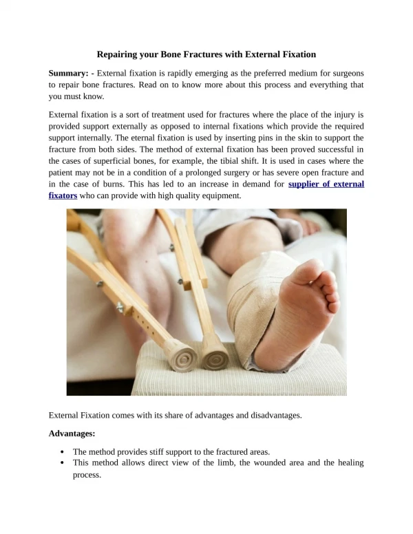
Biomechanics of External Fixation • Pin Size • {Radius}4 • Most significant factor in frame stability
Biomechanics of External Fixation • Number of Pins • Two per segment • Third pin
Biomechanics of External Fixation A C Third pin (C) out of plane of two other pins (A & B) stabilizes that segment. B
Biomechanics of External Fixation • Pin Location • Avoid zone of injury or future ORIF • Pins close to fracture as possible • Pins spread far apart in each fragment • Wires • 90º
Biomechanics of External Fixation • Pin Bending Preload • Bending preload not recommended • Radial preload (predrill w/ drill < inner diameter or tapered pin) • may decrease loosening and increase fixation
Biomechanics of External Fixation • Bone-Frame Distance • Rods • Rings • Dynamization
Biomechanics of External Fixation • SUMMARY OF EXTERNAL FIXATOR STABILITY: Increase stability by: 1] Increasing the pin diameter. 2] Increasing the number of pins. 3] Increasing the spread of the pins. 4] Multiplanar fixation. 5] Reducing the bone-frame distance. 6] Predrilling and cooling (reduces thermal necrosis). 7] Radially preload pins. 8] 90 tensioned wires. 9] Stacked frames. **but a very rigid frame is not always good.
= < Patient Load Patient Load Friction Force Patient Load Conventional Plate Fixation