Download
1 / 50
580 likes | 901 Vues
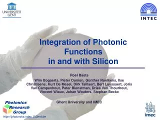
Integration of Photonic Functions in and with Silicon. Roel Baets Wim Bogaerts, Pieter Dumon, Günther Roelkens, Ilse Christiaens, Kurt De Mesel, Dirk Taillaert, Bert Luyssaert, Joris Van Campenhout, Peter Bienstman, Dries Van Thourhout, Vincent Wiaux, Johan Wouters, Stephan Beckx

E N D
Integration of Photonic Functions in and with Silicon Roel Baets Wim Bogaerts, Pieter Dumon, Günther Roelkens, Ilse Christiaens, Kurt De Mesel, Dirk Taillaert, Bert Luyssaert, Joris Van Campenhout, Peter Bienstman, Dries Van Thourhout, Vincent Wiaux, Johan Wouters, Stephan Beckx Ghent University and IMEC
Outline • why Silicon photonics? • sub-micron photonics in Silicon? • heterogeneous integration of III-V components onto Silicon?
Evolution of electronics... (IBM, mark1) 5 tons of components can multiply in 1 sec (pentium 4) 42 million transistors 2000 000 000 multiplications in 1 sec
Success of electronics? • Integrated circuits • economics of wafer scale integration • performance (smaller is faster!) • miniaturization in its own right • complex function can be made by a limited number of high-yield processes • focus on one production technology • few companies in the food chain • all efforts on the same material = Silicon
Should we integrate in photonics? • Yes! there are good reasons to do so • economics of wafer scale integration • performance • miniaturization • integrate with electronics • reduce costly optical packaging!!! • optical packaging is expensive! (often requires manual and/or active alignment at (sub)-micron level) • more integration = less packaging
The key bottleneck of photonic integration • (By far too) many degrees of freedom • many different materials • many different component types • many different wavelength ranges • Hence: • no generic integration technology for many different applications • no high volume technology platforms • too high cost • Hence: Integration is not an industrial reality (yet)
The way out - a roadmap • 1. Use mainstream Silicon(-based) technology • wherever possible, CMOS fab compatible • otherwise, use dedicated Silicon fab • 2. Add other materials where needed • for specialty functions • if the added value motivates it • 3. By using • wherever possible : wafer-scale post-processing technology (build-up) • otherwise, die-scale technology • 4. Build a photonic IC industry on this basis
Silicon-based photonic components and ICs • Many examples: • detector arrays and solar cells • CCD and CMOS-based image sensors • micro-displays • MEMS devices • LEDs • Silica-on-Silicon passive photonic ICs
CCD and CMOS-based image sensors • Several million pixels • High volume applications
1.8 cm 1.4 cm design by TFCG-IMEC Liquid Crystal microdisplay on CMOS Mosarel-project
Display www.dlp.com Digital Light Processing (DLP) Digital Mirror Device (DMD) MEMS based microdisplays
3-D CrossConnect Lucent Technologies, Bell Labs
Efficient Silicon-based LEDs • announced October 2002 by Salvo Coffa’s research team at ST Microelectronics • light emission from: • SiO2 layer, between p- and n-type Silicon • doped with rare earth ions by standard ion implantation • made conductive by Si nanoscale particles (1-2nm) • emission wavelength: • Cerium: blue • Terbium: green • Erbium: 1.55 micron • as efficient as III-V LEDs • next step: a laser???
doped SiO2 or SiOxNy SiO2 Si-wafer Silica on Silicon Arrayed Waveguide Grating -(de)multiplexer (AWG) Lucent
“Group IV photonics” 1st International Conference on Group IV Photonics Hongkong 29 September – 1 October 2004 Organized by IEEE-LEOS
Outline • why Silicon photonics? • sub-micron photonics in Silicon? • heterogeneous integration of III-V components onto Silicon?
1m 10m 100m 100nm 1mm 1cm Scale difference Electronics interconnects gate width transistor flip-flop Active opto-electronics detector Wavelength-scale photonics LED stripe laser VCSEL 2R regenerator taper spot-sizeconvertor Passive photonics fibre core Wavelength-scale photonics linewidth in current PIC AWG in Silica on Silicon Bend radius
WE NEED: Ultra-compact waveguiding with Sharp bends (Bend radius < 10m) Compact splitters and combiners Short mode-conversion distances Compact wavelength selective functions Highly dispersive element Small, high-Q resonators Compact non-linear functions Increase power density by using tight confinement Reduce PIC-size / increase density
High refractive index contrast (>2:1) • High refractive index • contrast allows for: • very tight bends • compact resonators with low loss • wide angle mirrors • very compact mode size • --> strong field strength--> strong non-linear effects • --> small volume to be pumped in active devices--> faster and/or lower power • photonic bandgap effects • high refractive index contrast is the key for ultra-compact photonic circuits semiconductor air dielectric
silica Si substrate Silicon-on-Insulator • Transparent at telecom wavelengths (1.55m and 1.3m) • High refractive index contrast • in-plane: 3.45(Si) to 1.0 (air) • out-of-plane: 3.45 (Si) to 1.45 (SiO2) • Compatible with CMOS processes Silicon
Photonic Crystal waveguides: in-plane: high contrastphotonic crystal defect out-of-plane: TIR Photonic Wires: in-plane: high contrast TIR out-of-plane: TIR Ultra-compact waveguide candidates
y z x M K x z y Guided Bloch mode conditions Radiation leak into substrate Coupling forw/backw Waveguide PBG guiding by PhC & SWG PBG Light line GuidedBloch Mode WG mode leak into PhC p/a GM GK p/a Brillouin Zone
Photonic Crystal Light is confined by the PBG Photonic Wire Deep etch allows for short bend radius (a few m) Corner mirrors Compact bends
Spectral accuracy and geometrical accuracy • High index contrast components: • - interference based filters, • with d the waveguide width () • - cavity resonance wavelength • with d the cavity length (a few ) • - photonic crystal • with d the hole diameter () if tolerable wavelength error : 1 nm tolerable length scale error : (of the order of) 1 nm
Photonic Crystal waveguides: in-plane: high contrastphotonic crystal defect out-of-plane: TIR Photonic Wires: in-plane: high contrast TIR out-of-plane: TIR Ultra-compact waveguide candidates • Both cases: • feature size : 50-500 nm • required accuracy of features: 1-10 nm • NANO-PHOTONIC waveguides
248nm excimer laser Lithography ASML PAS 5500/750 Step-and-scan Automated in-line processing (spin-coating, pre- and post-bake, development) 4X reticles Standard process 193nm excimer laser Lithography ASML PAS 5500/1100 Step-and-scan 4X reticles Deep UV Lithography for CMOS
AR-coating Photoresist Photoresist Si SiO2 Si-substrate Fabrication with deep UV Litho Bare wafer Photoresist(UV3) Soft bake AR coating Illumination (248nm deep UV) Resist trim Silicon etch Post bake Development Resist strip W. Bogaerts et al. Opt. Exp. 12(8) p.1583
Shallow etch, TE w Si 220nm SiO2 1m Si substrate SOI photonic wires w Propagation losses 400nm 440nm 450nm 500nm 33.8 9.4 7.4 2.4 ± 1.7 dB/cm ± 1.8 dB/cm ± 0.9 dB/cm ± 1.6 dB/cm
10m Ring resonators in Silicon on Insulator Photonic wire In Return bend ±2dB loss Through Drop Racetrack resonator 10m 3m
Racetrack Resonator 8m • Wire width = 510nm • TE polarisation • Q 12000 • 40% efficiency • FSR=16.5nm • Finesse=137 3.14m 4µm 0 pass port -5 -10 -15 normalized transfer [dB] -20 -25 drop port -30 -35 1524 1524.5 1526 1526.5 1525.5 1525 wavelength [nm] PTL 16(5) pp.1328-1330
AWG 200µm • 5 x 8 AWG, 400GHz spacing, 8 Channels • 300µm x 300µm area • -8dB loss in star couplers • - 6-10 dB crosstalk
Example: 6 stage CMZ 3.2nm bandwidth 17nm FSR coupling efficiency ~80% -10 dB crosstalk Cascaded MZ Filter pass normalized output [dB] drop gap width = 220nm waveguide width = 535nm wavelength [nm] waveguide width = 565nm L = 32.8µm 20µm 14µm 20µm 20µm 14µm 20µm
Outline • why Silicon photonics? • sub-micron photonics in Silicon? • heterogeneous integration of III-V components onto Silicon?
Integration of active components • light emitters with high efficiency and high modulation bandwidth III-V semiconductors • compact optical amplifiers III-V semiconductors • high speed detectors (in particular in IR) III-V semiconductors • high speed + compact optical modulators and switches III-V semiconductors
Integration of active + passive photonicsIntegration of active photonics and electronics • The options: • monolithic in III-Vcomplex and costly • Silicon-based IC + hybridly mounted III-V componentscostly + yield problem
Integrating electronics and photonics 2 4x8 VCSEL arrays 2 4x8 Detector arrays FPGA CMOS circuit + drivers + receivers
Integration of active + passive photonicsIntegration of active photonics and electronics • The options: • monolithic in III-Vcomplex and costly • Silicon-based IC + hybridly mounted III-V componentscostly + yield problem • direct epitaxy of III-V on Silicon • low III-V quality (so far) • bonding of III-V membranes on Silicon wafers (electronic or passive photonic)infancy stagebut looks promising
Bonded InP devices InP wafer SOI wafer bonding InP wafer substrate removal SOI wafer
Bonding technologies • Direct bonding (e.g. wafer fusion) • Metallic bonding (e.g. with solder) • Bonding with intermediate ‘glue’ layer e.g. BCB, SOG • …
Silica-Silica bonding Future: automated bonding of multiple InP dies to Silicon and subsequent substrate removal
Silicon electronics Silicon, passive micro-optics III-V die, active micro-optics Die-to-wafer bonding • Large size difference between III-V wafers (2-6”) and Silicon-wafers (8-12”) bonding of III-V islands on processed Silicon-wafer bonding must be low-temperature process (<450C) further wafer-scale processing of III-V devices after bonding Silicon wafer
InP membrane photonic crystal components • Building blocks for photonic integration • microcavities • low threshold optically pumped photonic crystal microlasers single line defect waveguide Lyon- / Viktorovitch-LEOM CNRS/ LEOS 2002-glasgow
polyimide polyimide InP substrate Si substrate Ti/Au contact BCB Si substrate top contact (n-contact) Si substrate Si substrate p-contact n-contact BCB Si substrate Si substrate Si substrate Si substrate InP membrane laser diode • Processing sequence:
InP membrane laser diode SEM photograph:
InP membrane laser diode Degradation tests: damp heat testing (85°C, 85% RH) for 48, 100, 250 and 500 hours PI IV Rs No observable degradation Further indication of bonding quality
Photonic wiring layer based on high index-contrast SOI or polymer waveguides Ultra-compact msources and mdetectors coupled to waveguides CMOS-wafer Application: FP6-PICMOS project • GOAL: Build Photonic Interconnect Layer on • CMOS by waferscale integration • Solve CMOS interconnect bottleneck • Use waferscale technologies, compatible with CMOS • Coordination: Dries Van Thourhout, Ghent University-IMEC, Belgium
PICMOS • Photonic Crystal Sources • Membrane type Photonic Crystal Sources coupled to underlying waveguide • Develop efficient electrical contacting scheme • Footprint < 100mm2 – Ith < 1mA – Bandwidth > 10GHz III-V PC laser Si waveguide (C. Seassal – CNRS-FMNT-LEOM)
Conclusions • Silicon-based photonics • The power of Silicon technology brought to the world of photonics • Silicon-based nanophotonics • Ultra-compact passive photonic ICs made by means of CMOS-technology • Active photonic components in III-V membranes bonded to Silicon • Wafer-scale approach to the integration of • Electronics • Passive (nano)photonics • Active (nano)photonics