Download
1 / 15
150 likes | 308 Vues
Integration of the CBM Silicon Tracking System. U . Frankenfeld for the CBM collaboration supported by BMBF, EU-FP7 HadronPhysics3 and CRISP. Location. FAIR. CBM. STS. STS Building Blocks: Module. STSxyter chip cable Sensor chip cable FrontEndBord FEB STSxyter chip.

E N D
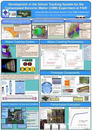
Integration of the CBM Silicon Tracking System U. Frankenfeld for the CBM collaboration supported by BMBF, EU-FP7 HadronPhysics3 and CRISP
STS integration Location FAIR CBM STS
STS integration STS Building Blocks:Module STSxyter chip cable Sensor chip cable FrontEndBord FEB STSxyter chip
STS integration STS Building Blocks:Ladder Carbon ladder Ladder sensor FEB cooling box Ladder
STS integration STS Building Blocks:Station Halfstation
STS integration Boundary conditions • Top down approach • From physics requirements to sensor layout and their mounting on ladders • Spatial requirements • Inside dipole Magnet • MVD upstream • RICH/MUCH downstream • Target and beam pipe • Mechanics • Precision • Stability • Thermal requirements • Sensor cooling • FEE cooling • Dry gas • Services • LV/HV • Cooling • Data and control
STS integration Magnet • Magnetic field in detector area 1 T • Working gap 1400x2500mm
STS integration STS Target MVD MVDenclosure Magnet Beampipe STS enclosure STSstations STS
STS integration Installation and maintenance Installation steps Maintenance requirements remove an arbitrary half station without dismantling the others Minimize removal of services remove an arbitrary ladder from a half station without dismantling the others Repair ladder Replace module • Assembly of modules to a ladders • Test of the ladder • Assembly of ladders to a half-station • Test of half-station • Installation and positioning of the half-stations into the STS box • Installation of the services • Test of STS • Insertion into the magnet
STS integration Dismantling sequence
STS integration Services Power Dissipation Services LV ~2000 Power domains ~40 kW HV 500 lines Cooling ~ 30 – 200 cooling line pairs Gaseous sensor cooling Nitrogen at -7°C Optical data links 484 Control lines • 212 Electronic blocks • ~40 kW power • Sensors • operation below -5°C • 1 mW/cm2 innermost sensors
STS integration Evaporative CO2cooling • LHCb VELO and AMS • R&D CERN and NIKEF • High heat transfer at small tube diameters • Active plant outside cave • CBM activities: • Cooling plant • Traci XL (1 kW) • FEB cooling efficiency Heat transfer (W/mm3K) Tube diameter (mm) http://cerncourier.com/cws/article/cern/49694
STS integration Jorge Sanchez - GSI/DetektorLab 720 Traci XL LEWA remote head pump (LDC1) 1 720 3 2 1060 671 2000 Extra space for vacuum pump min730 Sizing of the hydraulic pipe Adds: Extra pressure sensor after spiral Inlet for filling up the system Changes in MARCO Accumulator to adapt it to TRACI XL 1060
STS integration Cooling Mockup FEB cooling efficiency 200 W
STS integration Outlook: Integration approach • Workgroup with weekly meeting • Aim to get coarse CAD model fulfilling boundary conditions and including all services • Optimize in respect to operation and maintenance • Include details