Download
1 / 24
240 likes | 491 Vues
Flange- lok Installation Instructions. Quick Installation Guide 00825-0200-4809 rev. DB. Drill the Hole into the Pipe Using a Drill Bit or Hole Saw. Tag with correct drill hole size attached to the Annubar. Clean the Area with a Grinder to Prepare for the Surface for Welding .

E N D
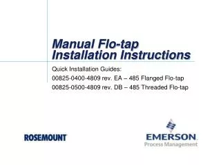
Flange-lok Installation Instructions Quick Installation Guide 00825-0200-4809 rev. DB
Drill the Hole into the Pipe Using a Drill Bit or Hole Saw Tag with correct drill hole size attached to the Annubar
Clean the Area with a Grinder to Prepare for the Surface for Welding
Mounting Should be Welded So the Bolt Holes are Parallel to Pipe • The mounting hardware should be gapped 1-/16th inch for welding • Use weld rod to do this • It should also be centered over the drilled hole
Tack Weld the Mounting Hardware with 4 Equal Length Tacks • Tack weld anywhere on the mounting hardware • Then again directly across from the first tack weld • Then on the other 2 sides 1 3 2
Check to See that the Mounting Hardware is Level and Square • If it’s not, use a rubber mallet to lightly adjust the hardware and recheck
Verify that the ODF Dimension Matches What is Listed in the QIG The ODF is the dimension from outside pipe diameter to face of flange
Tighten the Studs in Nuts in a Cross Pattern Until Appropriately Torqued
Mark the End of the Sensor With a Felt Tip Marker Do not mark if order with special cleaning (Option Code P2, PA)
Insert the Flowmeter Until the Tip Contacts the Opposite Side Pipe Wall Rotate Annubar back and forth.
Remove the Flowmeter and Verify the Sensor Tip Made Contact Some of the marker should have been rubbed off.
Insert a Packing Ring Underneath the Compression Plate and the Follower The split in the packing ring should face one of the three studs. Use the Compression Plate and Follower to compress the packing into the Pak-lok Body.
Packing Goes Below the Compression Plate and Follower NO! Packing Follower Compression Plate Weld Ring YES! NO!
The Next 2 Packing Rings should be Inserted so the Split is 120۫ Apart The split in each packing ring should face a different stud which are 120 degrees apart
Insert the Second Packing Ring with the Split Facing a Different Stud Compress it with the Follower and Compression Plate
Insert the Third Packing Ring with the Split Facing a Different Stud Compress it with the Follower and Compression Plate
Tightened the Nuts Until the Split-Ring Washers are Flattened The Split-Ring washers are specially designed to be flat at the appropriate Torque level for the Annubar