OLI Overview and Status
OLI Overview and Status. Landsat Science Team Meeting 6/23/09. Outline. Instrument Overview Subsystem Status Preliminary Data and Performance Predictions Conclusion. Instrument Overview. OLI Maintains Landsat Legacy. Key instrument parameters Cross-track FOV 185 km


OLI Overview and Status
E N D
Presentation Transcript
OLI Overview and Status Landsat Science Team Meeting 6/23/09
Outline • Instrument Overview • Subsystem Status • Preliminary Data and Performance Predictions • Conclusion
OLI Maintains Landsat Legacy • Key instrument parameters • Cross-track FOV 185 km • S/C altitude 705 km • Geodetic accuracy* • Absolute 65 m • Relative 25 m • Geometric accuracy** • Absolute 12 m • Landsat Continuity Mission demands • Accurate spectral and spatial information • Frequent synoptic earth views • NIST calibrated over time • Precise geo-referenced data Coastal/Aerosol and Cirrus bands are new; NIR and Pan are narrower; bandpasses of others equivalent Visible/NIR SWIR *No terrain compensation **w/ terrain compensation Note: Geometric reqts are tighter for OLI
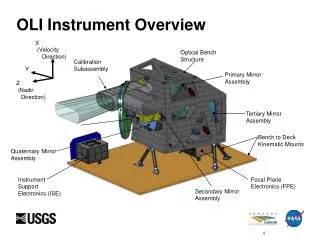
OLI is a fairly simple instrument • Pushbroom VIS/SWIR sensor • Four-mirror telescope with front aperture stop • FPA consisting of 14 sensor chip assemblies, passively cooled • On-board calibration with both diffusers and lamps
Major Changes since last Science Team Meeting Locked down final thermal design Small changes to heaters, thermistors, blankets, radiators from ICDR design Silicon Detector Anomaly resolved Problem with stability over time identified; new detectors in work Built up most of telescope Mirrors installed and aligned (TBR) Stim Lamp Assemblies complete and ready for installation Kinematic Mounts complete and ready for installation Light Baffles complete Changed internal coating to reduce stray light
Key Technical Parameter (KTP) Performance Summary Meeting all key requirements with margin Changes since last Science Team Finalization of Baseplate Design and impacts on Power and Mass Steps to improve power margin are underway; not expected to be an issue Performance predictions now incorporate actual optics measurements Very close to original models Mass and power are reported for both current best estimate (CBE) and “mature” values, which include Ball Aerospace growth factors “Current Best Estimate” is the designer’s estimate Mature mass / mature power reflects historical growth. i.e., it’s contingency
Optical Mirrors Complete Primary Secondary Tertiary Quaternary
Main Bench Assembly Completed Side View of Bench Back View of Bench
Telescope Build Telescope install in Universal Test Fixture (UTF) Telescope roll in UTF FPA Mounting in Telescope UTF Install into Wedge Assy First “look” through telescope Tele in UTF
Focal Plane Consists of 14 Modules • Each Module contains Silicon and HgCdTe detectors mounted on a single readout chip (ROIC) • Spectral Filters above the detectors provide separation into bands Focal Plane Module
Engineering Development Unit FPA complete Will retrofight a “flight” quality window later this summer Will reduce ghosting Flight FPA parts proceeding on schedule Will be waiting for the flight detectors
OLI image quality will depend on focal plane module uniformity Need filters and detector responses to be ‘the same’ (<0.5%) for all 14 FPMs Need precise alignment to eliminate clocking or other errors (will be known prelaunch) Eliminate seams and bowing effects Have to account for timing differences between pixels in image reconstruction Possible seams FPM Possible clocking Timing Lag Filters over detectors Possible bowing
EDU Preliminary X-Y Alignment Results Well within requirement (green circle) Y Alignment Error X Alignment Error
Silicon Detector Anomaly identified and resolved • Post-delivery measurements identified a degradation in some silicon detectors • Charge was diffusing into neighboring regions around pixels—no longer acting like a “detector” • Degradation was very slow (months) • Aggressive technical team (Goddard, BATC, Raytheon) worked through data and identified root cause • Not discussed here for ITAR reasons • Decision was to make new detectors for flight • Initial material manufactured; looks very good
Focal Plane Electronics Status • Modified biases to accommodate new silicon flight detector design • Part of eliminating the anomaly conditions • Most flight boards near completion • Examples below EDU Board with Bias Change EDU FPE
Focal Plane Testing • Have completed testing on Engineering Model Focal Plane Modules • Conducted radiometric, spectral, spatial, ghosting tests • Select results toward the end • Now testing at Focal Plane Subsystem level with Engineering Model • More Radiometric and Spatial Testing • Will also look at Stability and first “Image” New, very bright integrating sphere for radiometric testing
Flight Electronics Boards being completed GHC board #1 SHC board
Thermal Control Design Unchanged +X UP ORIENTATION FPA Radiator Support Truss FPA Heat Pipes FPA Design integrated onto instrument FPE Radiator FPE Heat Pipe Support FPE Heat Pipe
Calibration Subsystems in Manufacture • Calibration Subassembly Consists of Five Subassemblies • 3 LightShade Assemblies • 1 Diffuser Assembly • 1 Shutter Assembly • Stim Lamp Assemblies redesigned to increase emitted light and optimize monitoring diode position Solar LightShade Aft LightShade Entrance LightShade Diffuser Assembly Shutter Assembly Diodes view diffuser instead of housing wall No direct view of any lamps Exploded View of Calibration Subassembly
Stim Lamp Assemblies Complete and in Test • Have been attached to aperture • Completed radiometric testing • Signals good • Completed Environmental Testing • Ready for integration into telescope
Coding of Ball Aerospace Algorithms Into Continues—Next “drop” expected later this year Ball On-Line Processing Ball Off-Line Processing LDCM IPE Ball Data Analysis System Data Ingest Radiometric Processing Geometric Processing Product Generation Ball Performance, off-line Analysis, Track and Trend Tools LDCM Archive database 1. L0 Image Construction 2. Prepare Ancillary Data for Input to Ball Code Retrieve Data Parse Data Ball/LDCM Archive database Radiometric Processing Geometric Processing Product Generation LDCM CPF Ball Calibration Parameter Files (CPF) Evaluation of Results yes yes Update no • Changes Since last meeting • Grouping of modules in data ingest • On-line cal algorithms append Ball CPFs Processing Algorithm Stop Radiometric Algorithms Collaborative Decision Geometric Algorithms
Ghosting looks good: Only Expected Internal Window Ghost Present – Along Track Scans - 10 Pixel Posn 10 Pixel Reqt 30 Pixel Posn 30 Pixel Reqt Band = 2 (Blue) 0 10 -1 10 SCAN 2 Internal Window Ghost -2 10 Ghosting Isolation -3 10 -4 10 SCAN 1 -5 10 0 100 200 300 400 500 600 700 pixel * Results plotted for single pixel in middle of array; all pixels consistent
Cross-Track Scan Results – Blue Compliant, no Ghost No Ghost near requirements Potential broadening, but still meets reqts 10 Pixel Posn 10 Pixel Reqt 30 Pixel Posn 30 Pixel Reqt SCAN3 SCAN 4
0 10 -1 10 -2 10 -3 10 -4 10 -20 0 20 40 60 80 100 FPM Ghosting Data Shows Good Correlation with Stray Light Model - PAN • Ghost Measurements • AT Scan • PAN Band • 1.5 Source (diagonal) • 1.2 x 0.8 Source GSE Window Internal Ghost * Measured Data GSE Window Internal Ghost * Measured Data Model Prediction Model Prediction Requirement – 10 pix Ghosting Isolation Requirement – 10 pix Requirement – 30 pix Requirement – 30 pix Distance (pixels)
Spectral Response for VNIR Bands looks good • In general, VNIR results are meeting requirements with margin • The VNIR bands meet non-integrated and integrated OOB response
Some EDU FPMs have OOB response that does not meet the non-integrated OOB requirement Plot to left shows how SWIR2 was responding to SWIR1 light Was not present on all FPMs Was not present for all detectors Proved it was not a filter problem Swapped filters between a ‘good’ and ‘bad’ FPM—crosstalk remained with detectors Established a very strong correlation with quantum efficiency Those detectors that had poor QE also have crosstalk Which led to a screening test Screen detectors for QE (already being done); reject those that do not meet new threshold requirement No meaningful impact on schedule or performance expected Crosstalk was detected in some SWIR out-of-band response measurements—being mitigated
Summary • Hardware is starting to roll in • Artifacts have been identified, caught, and are being corrected for flight • Performance predictions look good