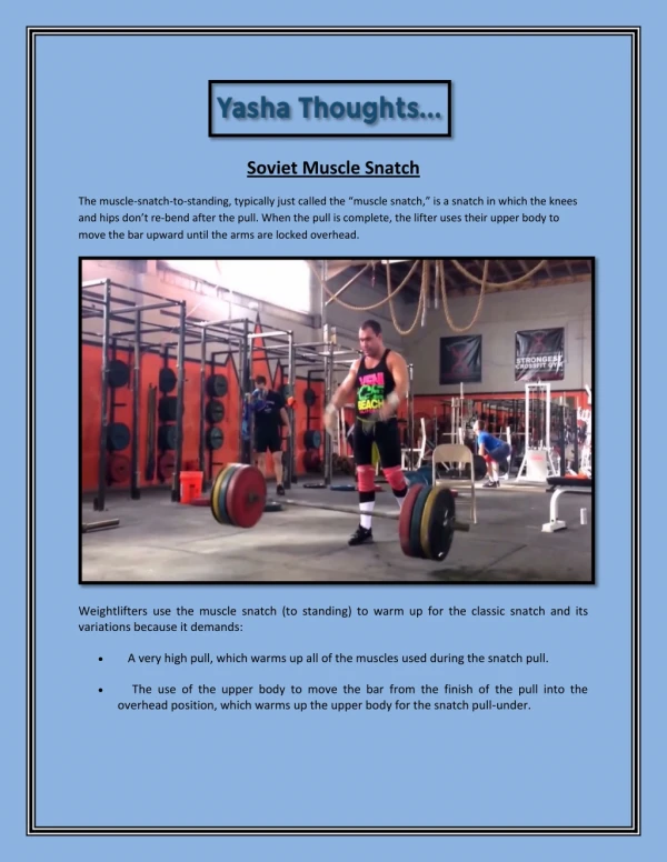

Understanding Snatch Block Assembly in Mechanical Engineering
E N D
Presentation Transcript
Snatch Block Assembly PRITI S VAIRAGI MECHANICAL ENGINEER
PULLEYS • Pulleys are manufactured in fixed and movable designs. • Pulleys with fixed axles are also guiding because they change the direction of flexible hoisting appliance. • A rope and pulley system that is, a block and tackle is characterized by the use of a single continuous rope to transmit a tension force around one or more pulleys to lift or move a load the rope may be a light line or a strong cable. • If the rope and pulley system does not dissipate or store energy, then its mechanical advantage is the number of parts of the rope that act on the load.
Different types of pulley systems are as follow • Fixed Pulley • Movable Pulley • Multiple pulley system
Multiple pulley systems • The following shortcomings due to direct suspension of loads from the rope end or from employing simple pulleys for a gain in force in hoisting appliances can be pointed out. • 1. The rope parts in one plane and this may cause the load to sway • 2. Large diameter of ropes and pulleys • 3. The load being lifted moves in a horizontal direction because a rope coiling on a drum moves along its length. • These shortcoming can be avoided, especially in the hoisting mechanisms of winches and cranes with an electric drive, by using multiple pulley systems which raise the load in strictly vertical direction and keep it more stable. • These systems carry the load with twice as many parts as a similar pulley system.
In crane design, always multiple pulley system are used. • Multiple pulley system is also known as multifall system. • It is done to get mechanical advantage and to reduce the load per strand of rope. • It enables us to use small cross-section of rope. • This in turn reduces the size of pulley and cost of pulley. • So that for assembly we can go for light weight construction.
Fall system corresponding to different loads and efficiency of pulley system
Bend • Bend is considered as a point where there is relative motion between the rope and the pulley and where rope either moves over the pulley or leaves the pulley. • A bend is considered as double bend where direction of pulley changes and rope undergoes complete reversal of spaces. • Life of rope is always depends on number of bends. • Hence select system with minimum number of bends so that life can be increased. • In order to reduce the stresses in the rope it would be necessary to increase the diameter of pulley. Hence as number of bends increases, 𝑫𝒑 /𝑫𝒓 ratio increases.
Following figure show the bend measurement for two cases. • 1. Bend toward same side, 2. Reverse bend
Compensating Pulley • Compensating pulley is located at the centre of the system and in normal course, compensating pulleys do not rotate. • If for lifting purpose, the hook assembly is pulled on one side then only the compensating pulley will rotate and adjust the length of rope. Sometimes for higher heights, the weight of the ropes in the suspension will cause an imbalance on the driving mechanisms. The ropes over the compensating pulley help in maintaining appropriate balance. • Compensating pulley diameter can be considered as 60 percent of the movable pulley diameter.