Download
1 / 14
140 likes | 291 Vues
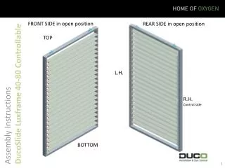
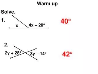
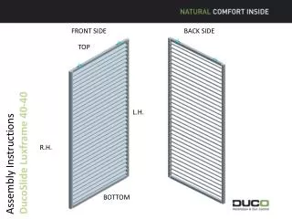
FRONT SIDE. BACK SIDE. TOP. Assembly Instructions DucoSlide Luxframe 40-40. L.H. R.H. BOTTOM. Parts Breakdown. Parts Breakdown. Parts Breakdown. Parts List All cut lengths of the individual parts are specified in the parts list.

E N D
FRONT SIDE BACK SIDE TOP Assembly Instructions DucoSlide Luxframe 40-40 L.H. R.H. BOTTOM
Parts List • All cutlengths of the individualparts are specified in the parts list. • The distance “center onderste gat tot zaagsnede” (center-to-centerdistancefrombottom hole to cuttingline) is to beusedforcutting the punchedsections to length.Thisdistanceshouldbepassed to the productiondepartment.
MOUNTING SEQUENCE • 1. Sizing • * Cut both the top rail and the bottom rail off square : length = slide width - 80 mm (twice the width of the stile). • * Cut the blades to the same length as the top and bottom rail. • * Cut a LH and a RH vertical pre-punched profile down to size taking into account the symmetric distribution of the hole pattern : length = slide width – 6 mm (twice the width of the cover plate). Since the cover cap is not cut at the same time as the vertical profile, a - 0.5 mm up to - 1 mm tolerance on the length of the vertical profile needs to be taken into account to make sure the cover cap can be retrofitted.
2. Mounting Preparations • * Using the drilling jig, drill 6.2 mm holes in the top and bottom of the vertical profiles. Make sure the drilling jig is a tight fit against the extreme end of the vertical profiles and hold it in position using a quick action clamp or an F-clamp.
3. Fitting the Slide Make sure to use the correct screw bit for each type of screw drive (PH 2, Pz 2, PZ 3) and adjust the tightening torque of the drill/screwdriver to the screws involved. • * Fit a cover plate to either end of the vertical profiles using two A2 stainless steel M4 x 20 DIN 7500 Form M screws with PZ 2 drive. • * Slide the top and bottom rail, with the visible drill groove facing outwards, in between the vertical profiles and secure them on one side using A2 stainless steel M6 x 25 DIN 7500 Form C screws with PZ 3 drive for each rail. For the other vertical profile, screw the screws a few turns leaving enough room for the blades to be a sliding fit. • * Place the blades in the positioning jig and make sure the blades on both the front and the backside lie flush with the stile, first and then fix each in place on one side using two A2 stainless steel M5 x 20 DIN 7500 Form C screws with PZ 2 drive. On the opposite side, tighten each screw by only a few turns.
That's how the positioning jig looks like. • * Now push the remaining vertical profile fully home against the already assembled items. Firmly tighten the screws of the top and bottom rail first and then those securing the blades. • * Check the slide for squareness by taking measurements across the diagonals using a tape measure. • * Where appropriate, make sure you have the slide flat on a tabletop if it does not fit flat against (tilted to one side) this work surface. • * Fit the cover caps to the vertical profiles.
4. Fittings Mounting • * Place the suspension bracket (G0013031 or G0013080) • on the top rail of the slideusing the positioningjig. Be sure the hole provided in the suspension bracket, to accommodate the suspension bracketscrew, pointstowards the rear of the slide. Fastenitwithfour A2 stainless steel M 4.8 x 18 self-drillingscrewswith PH 2 drive, to DIN 7504-M (G0000227). Do thisforbothsides of the slide. • * A choice of threepossiblefixingpositions of the suspension bracket (G0013031 or G0013080) is available: • These positionsvarydependinguponwhat the customerordered ! • Standard position at 150 mm, formanuallyoperatedslides ; • underneath the actuator at 200 mm, formotorized single slides ; • Withmotorizedsymmetricalslides : underneath the actuator at 200 mm ; in the center at 2 x 100 mm ; at the return pulley at 150 mm ; • Withmotorizedtripleslides : underneath the actuator at 200 mm ; at the oppositeside of the motorized actuator at 170 mm ; the othertwoslides at 150 mm. • These different positionscanbe set byshifting of removing the pin, dependingon the positionby the suspension bracket.
* Place the bottom guide base ( G0013003) (G0013031) on the bottom rail of the slide using the positioning jig. Fasten it with an A2 stainless steel M 3.9 x 19 self-drilling screw with PH 2 drive, to DIN 7504-O (G0100528). Do this for both sides of the slide.
CE label • Put the CE-labelon a visible spot, forexampleon the side of the frame (do not put itonthe blades) • Makesure the label fits goodon the frame.