Download

1 / 23
250 likes | 451 Vues
FRONT SIDE in open position. REAR SIDE in open position. Assembly Instructions DucoSlide Luxframe 40-80 Controllable. TOP. L.H. R.H. Control side. BOTTOM. FRONT SIDE in closed position. REAR SIDE open - closed. Cross-section. Detail cross-section A-A. Parts Breakdown.

E N D
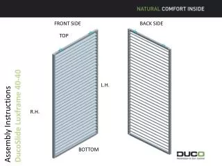
FRONT SIDE in open position REAR SIDE in open position Assembly Instructions DucoSlide Luxframe 40-80 Controllable TOP L.H. R.H. Control side BOTTOM
FRONT SIDE in closed position REAR SIDE open - closed
Cross-section Detail cross-section A-A
Parts Breakdown • S5000500 LH head piece set • G0100550 LH Linear 115 series head piece • G0100520 Spring pin • G0008305 Track stopper • G0000113 Csk self tapping screw, DIN 7500, M6 x 30, A2 stainless steel – 2 items S5000501 RH head piece set G0100555 RH Linear 115 series head piece G0100520 Spring pin G0100531 Spring (head piece) G0008305 Track stopper G0000113 Csk self tapping screw, DIN 7500, M6 x 30, A2 stainless steel – 2 items • S5000502 Locking set for RH head piece • H0100555 RH Linear 115 series head piece specific for locking set • G0100532 spring (lock) • G0100531 Spring (head piece) • G0100520 Spring pin • G0008305 Track stopper • G0100510 Lever • G0100505 Locking pin S5000503 Mobile pivot point set G0100515 Mobile pivot point set G0000137Adjusting screw, DIN 914, M5 x 6, A2 stainless steel G0100500 Lock housing G0000034screw DINØ 3.9 x 9, A2 stainless steel, countersunk head with PH 2 drive G0000113 DIN 7500, self-tapping CSK head screw, M6 x 30, A2 stainless steel – 2 items 0.G0100523Setting scale
Fitting Sequence • 1.Cutting to length: • * Cut both the top rail and the bottom rail off square : length = slide width - 80 mm (twice the width of the stile). • * Cut the louvre blades to size : length = slide width - 80 mm (2 x width of the stile) - 25 mm (head piece room and clearance). • * Cut one L-shaped profile 50 x 20 x 2 to size : length = louvre blade length • * Cut two prepunched vertical profiles to size : length = slide height - 6 mm (2 x the thickness of the cover plate). The cover cap is not cut at the same time as the vertical profile, a - 0.5 mm up to - 1 mm tolerance on the length of the vertical profile needs to be taken into account to make sure the cover cap can be retrofitted. The bottom hole for the louvre blade is at 100 mm from the bottom of the profile.
Fitting Sequence • * The operating rod may vary in length when the number of louvre blades is odd. The length of the top rod = (number of louvre blades of the top section – 1) x 105 + 15 mm ; the length of the bottom rod = (number of louvre blades of the bottom section – 1) x 105 + 15 mm. • 2.Mounting Preparations for Slide Frame • * Using the drilling jig, drill, drill 6.2 mm holes at the top and bottom of the vertical profiles. Make sure the drilling jig is a tight fit against the extreme end of the vertical profiles and hold it in position using a quick action clamp or an F-clamp.
Fitting Sequence • 3Pre-installing the Slide Frame • * Fit a cover plate to either end of the vertical profiles using two A2 stainless steel M4 x 20 DIN 7500 Form M screws with PZ 2 drive. • * Insert the Igus bearings via the inside of the stiles in the 9 holes until their collars can be felt to abut against the face of the profile. Press firmly. This is not required for the top and bottom holes since no louvre blade will be inserted at these locations. • * Split the number of 9 mm holes in the side profiles of the slide evenly over two parts. When the number is odd, take one hole more for the bottom half than for the top half. Slides small in height may have only one setting scale fitted. The fixing position is at the instructions of the technical drawing department or to the clients individual choice.
Fitting Sequence • * Slide the top section setting scale over the Igus bearings of the second and third • louvre blades starting from the middle part. • But slide the bottom section setting scale over the two top Igus bearings. • Make sure to always secure the setting scales to the RH side profile with two DIN 7504 Form O, M9 x 19, A2 stainless steel self drill screws with PH 2 drive.
Fitting Sequence • * Fit the corner-angle reinforcements into the top profile. • * Slide the top and bottom rail, with the visible drill groove facing outwards, in between the vertical profiles and secure them on both sides using four A2 stainless steel M6 x 25 DIN 7500 Form C screws with PZ 3 drive for each rail. • * Check the slide for squareness by taking measurements across the diagonals using a tape measure.
Fitting Sequence • 4. Fittings Mounting • * Place the suspension bracket (G0013031 or G0013080) on the top rail of the slide using the positioning jig. Fasten it with four A2 stainless steel M 4.8 x 18 DIN 7504-M self-drilling screws with PH 2 drive (G0000227). Do this for both sides of the slide. • A choice of three possible fixing positions of the suspension bracket (G0013030) is available : At 150 mm for the standard configuration, at 195 mm for telescopic and symmetric slides on the return pulley side and at 260 mm for the side of the slide underneath the actuator. • * Place the bottom guide base (G0100700) on the bottom rail of the slide using the positioning jig. Fasten it with an A2 stainless steel M 3.9 x 19 self-drilling screw with PH 2 drive, to DIN 7504-O (G0100528). Do this for both sides of the slide.
Fitting Sequence 5. Fitting the Trim Profile Place the L-shaped profile in the centre of Lux 80 series top profile with the 50 mm side facing the front of the slide (12.5 mm open on both sides). Fasten the L-shaped profile every 200 mm with M 3.5 x 13 DIN 7504 self-drilling screws (G0000080) ; always start a 50 mm from the edge.
Fitting Sequence • 6. Pre-Installing the Blades • S5000500 LH head piece set • Insert a spring pin and a protective cap in the head piece. • Make sure every louvre blade has a spring pin and a protective cap inserted which are both fixed with two A2 stainless steel M6 x 30 screws with PH 3 drive, to DIN 7500-M (G0000113). • S5000501 RH head piece set • Insert a spring pin, a spring (G0100531) and a protective cap in the head piece. • Fasten each set of these three items two A2 stainless steel M6 x 30 screws with PH 3 drive, to DIN 7500-M (G0000113). LH Head Piece Assembly S5000500 RH Head Piece Assembly S5000555
Fitting Sequence • Locking Set S5000502 • Insert a spring pin, a spring and a protective cap in the head piece. • Ease the lock housing into the T14036-11louvre blade until the slotted holes of the lock housing and the louvre blade are facing one another. • Fasten with two A2 stainless steel M3.9 x 9 screws, DIN 7982. • First slide spring G0100532 in the tapped hole of the housing and, next, the lock pin. • Secure the assembly turning the lever of the slotted hole into the lock pin. • Fit the head piece on this side of the blade using two A2 stainless steel M6 x 30 screws with PH 3 drive, to DIN 7500-M (G0000113). RH Head Piece Locking Pin S5000502
Fitting Sequence • 7. Pre-Installing the Operating Rods • * Make sure each pivot point has an A2 stainless steel M5 x 6 cone point grub screw (DIN914) inserted, and be sure the screw is not apparent through the hole to accommodate the operating rod. • * Fit a protective cap at either end of the operating rod. • * Secure the top pivot point to the operating rod with only the protective cap protruding. Ensure the pivot points in-between are a free fit on the operating rod. Lightly tighten the lowest pivot point, with only the protective cap protruding, as to prevent the pivot points in-between from dropping. Only fix the top or bottom pivot point.
Fitting Sequence • 8. Fitting Louvre Blades into the Frame • * Place the pre-installed frame with its back down on a table (the 9 mm holes with the Igus bearings at the top). • * Start with the louvre blades with an integrated lock. • - Insert the locating pin in the bearing directly opposite the centre of the setting scale. • - Present the extended catch on top of the frame and compress the spring pin. Bring the pin opposite the bearing in the centre of the setting scale so as to allow it to fit into the hole. • - Fit a circlips to either end of the spring pin. • - Pull the catch back and turn the louvre blade for the catch to snap into place in the hole of the setting scale.
Fitting Sequence • * Next, proceed with fitting the remainder of the louvre blades. • - Insert the locating pin into the same side as with the prior louvre blades. • - Keep the spring pin compressed, place it so that it faces the opposite bearing first and then release the spring pin so that it fits into the hole. Allow the lug for louvre blade control to continue to turn up to the table top. • - Locate a circlips over the pins at either end. Start with the locating pin and then move to the spring pin.
Fitting Sequence • 8. Fitting and Adjusting the Operating Rods • * Turn the slide over with the front facing you ; ensure the frame rests on the side profiles and that the louvre blades are suspended downwards. (By preference, use plastic strips to ensure the coating cannot be damaged.) Move all louvre blades up using the control lug. • * Insert the pre-installed operating rod with the top pivot point into the lug of the top louvre blade (if there are 2 different lengths, position the longest at the bottom or follow the indications of the technical drawing department). Fasten it with an A2 stainless steel M5 x 10 csk socket head button screw, to ISO7380. Next, insert the pivot points, one at a time, into the next louvre blades and screw the socket head button screws a few turns each time. Once all the pivot points are in position, tighten the socket head button screws fully. • Do this for both operating rods.
Fitting Sequence • *Next, carefully close the louvre blades. Position the louvre blades with the catch in the closed position so that the louvre blades form a closed area. • * Move the supports that are under the frame: Position them under the louvre blades so that the frame floats. In so doing, all louvre blades are forced to lie in one plane. • * Start at the top with tightening the adjusting screws to secure the pivot points to the operating rod. Keep the lug of the blade pressed against the previous blade and tighten the adjusting screw. Do the same for all pivot points.
CE label • Put the CE-labelon a visible spot, forexampleon the side of the frame (do not put itonthe blades) • Makesure the label fits goodon the frame.