SolidWorks Simulation
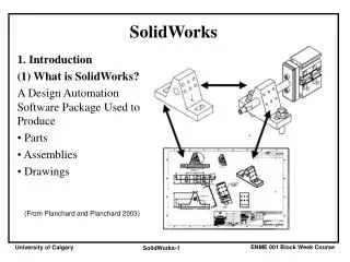
SolidWorks Simulation. What is SolidWorks Simulation?. it is a design analysis software that is fully integrated in SolidWorks. it simulates the testing of your model’s prototype in its working environment


SolidWorks Simulation
E N D
Presentation Transcript
What is SolidWorks Simulation? • it is a design analysis software that is fully integrated in SolidWorks. • it simulates the testing of your model’s prototype in its working environment • it can help you answer questions like: how safe, efficient, and economical is your design? will it bend? will it break?
EGM 3520 – Mechanics of Materials • analytical solutions are presented for a variety of problems axial loading torsion bending
EGM 3520 columns beams
EGM 3520 multiple loading
The Finite Element Method • Analytical solutions are only available for simple problems. They make many assumptions and fail to solve most practical problems. • SolidWorks Simulation uses the Finite Element Method (FEM). Analysis using the FEM is called Finite Element Analysis (FEA) or Design Analysis. • FEA is very general. It can be used to solve simple and complex problems. • FEA is well-suited for computer implementation. It is universally recognized as the preferred method of analysis. EML 4507
Main Concept of Design Analysis The FEM replaces a complex problem by many simple problems. It subdivides the model into many small pieces of simple shapes called elements. CAD Model CAD Model Subdivided into Small Pieces
Main Concept of Design Analysis • The elements share common points called nodes. The behavior of these elements is well-known under all possible support and load scenarios. • The motion of each node is fully described by translations in the X, Y, and Z directions. These are called degrees of freedom (DOF). Each node has 3 DOF.
Main Concept of Design Analysis • SolidWorks Simulation writes the equations governing the behavior of each element taking into consideration its connectivity to other elements. • These equations relate the unknowns, for example displacements in stress analysis, to known material properties, restraints, and loads. • Next, the program assembles the equations into a large set of simultaneous algebraic equations. There could be hundreds of thousands or even millions of these equations.
Types of Analyses • static • nonlinear • buckling • frequency (vibrations) • thermal • optimization Fluid flow analysis is performed in a different module, i.e. SolidWorks Flow.
Types of Analysis: Static or Stress Analysis • This is the most common type of analysis. It assumes linear material behavior and neglects inertia forces. The body returns to its original position when loads are removed. • It calculates displacements, strains, stresses, and reaction forces. • A material fails when the stress reaches a certain level. Different materials fail at different stress levels. With static analysis, we can test the failure of many materials.
What is Stress? • When a load is applied to a body, the body tries to absorb the effect by generating internal forces that vary from one point to another. • The intensity of these forces is called stress. Stress is force per unit area. • Stress at a point is the intensity of force on a small area around that point.
What is Stress? • Stress is a tensor quantity described by magnitude and direction in reference to a certain plane. Stress is fully described by six components: • SX: Normal stress in the X-direction • SY: Normal stress in the Y-direction • SZ: Normal stress in the Z-direction • TXY: Shear stress in the Y-direction on YZ-plane • TXZ: Shear stress in the Z-direction on YZ-plane • TYZ: Shear stress in the Z-direction on XZ-plane • Positive stress indicates tension and negative stress indicates compression.
Principal Stresses? Shear stresses vanish for some orientations. Normal stresses at these orientations are called principal stresses. • P1: Normal stress in the first principal direction (largest). • P2: Normal stress in the second principal direction (intermediate). • P3: Normal stress in the third principal direction (smallest).
von Mises Stress • von Mises stress is a positive scalar number that has no direction. It describes the stress state by one number. • Many materials fail when the von Mises stress exceeds a certain level. • In terms of normal and shear stresses, von Mises stress is given by: • In terms of principal stresses, von Mises stress is given by:
Analysis Steps • Create a study to define the type of analysis. • Define material for each component. • Apply restraints and loads. • Mesh the model. This is an automatic step in which the program subdivides the model into many small pieces. • Run the analysis. • View the results. • Steps 2, 3, and 4 can be done in any order.
Creating a Study • The first step in analysis using SolidWorks Simulationis to create a study. • A study simulates a test case or a what-if scenario. It defines analysis intent (type), materials, restraints, and loads. • You can create many studies and the results of each study can be visualized at any time.
Defining Materials • Results depend on the material used for each component. • You can select a material from the library or you can define material properties manually. • You can also add your own material properties to create customized material libraries. • Materials can be isotropic or orthotropic. Isotropic materials have the same properties in all directions. Orthotropic materials have different properties in different directions (like wood).
Defining Restraints and Loads • Restraints define how the model is supported. A body that is not restrained may move indefinitely as a rigid body. • Adequate restraints should be applied to prevent rigid body motion. • Loads include forces, pressure, torque, centrifugal, gravitational, prescribed nonzero displacements, and, thermal loads. Special options for bearing and remote forces are also available.
Meshing • Meshing subdivides the model into many small pieces called elements for mathematical simulation. • Smaller elements give more accurate results but require more computer resources. • The program suggests an average global element size for meshing. This is the average length of an element side. • In critical regions (concentrated loads, irregular geometry) you can apply Mesh Controlto reduce the element size and improve the accuracy of results.
Meshing Types • You choose the Mesh Type when you create a study. You can choose: Solid Mesh, Shell Mesh Using Mid-Surfaces, Shell Mesh Using Surfaces, Mixed Mesh, and Beam Mesh. • Use Solid Mesh for bulky models. • Use Shell Mesh Using Mid-Surfaces for thin simple models with constant thickness. • Use Shell Mesh Using Surfaces to create shells with different thicknesses and materials on selected faces. • Use Mixed Mesh when you have bulky as well as thin bodies in the same model. • Use Beam Mesh to model structural members.
Meshing • Based on the element size, the program places points (nodes) on the boundaries and then it fills the volume with 3D tetrahedral elements for solid mesh or 2D triangular elements for shell mesh. • You must mesh the model after any change in geometry. Material, restraint, and load changes do not require remeshing.
Using Symmetry • Using symmetry reduces the problem size and improves results. • Symmetry requires that geometry, loads, material properties, and restraints are symmetrical. • Requirements of symmetry restraints: • Solid models: All faces that are coincident with a plane of symmetry are prevented from moving in the normal direction. • Shell models: All edges that are coincident with a plane of symmetry should be prevented from moving in the normal direction and rotating about the other two orthogonal directions. • Symmetry restraints should be avoided in frequency and buckling studies. Model symmetrical with respect to one plane. Half of the model with symmetry restraints applied.
Shell Mesh • You can use shell mesh instead of a solid mesh to model thin parts. Shell elements resist membrane and bending forces.
Running Analysis • After defining materials, applying restraints and loads, and meshing your model, you run the analysis. • During analysis, the program calculates the results. This step includes intensive number crunching. In many cases the program will be solving hundreds of thousands of simultaneous algebraic equations. • SolidWorks Simulation has state-of-the art, fast and accurate solvers.
Visualizing Results • After completing the analysis, you can visualize the results. • SolidWorks Simulation provides advanced easy-to-use tools to visualize the results in few clicks. • Use section and iso plots to look inside the body. • The Design Check Wizard checks the safety of your design for static studies. • SolidWorks Simulation generates a structured Internet-ready report for your studies.
Finite Element Analysis Process – Model part and specify material 6061 T6 aluminum 4” .25”
Apply Loads 2000 N distributed across face