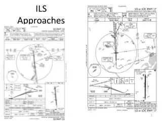
ILS Approaches
ILS Approaches. ILS Approach Nomenclature. ILS Converging ILS ILS or LOC ILS LOC ONLY N/A ILS Y & Z designators indicate important differences (IAP’s, FAP’s, MAP’s, FAC’s, Minimums, etc.) between multiple approaches to the same runway using the same base navigation equipment ILS RNAV/GPS

ILS Approaches
E N D
Presentation Transcript
ILS Approach Nomenclature • ILS • Converging ILS • ILS or LOC • ILS LOC ONLY N/A • ILS Y & Z designators indicate important differences (IAP’s, FAP’s, MAP’s, FAC’s, Minimums, etc.) between multiple approaches to the same runway using the same base navigation equipment • ILS • RNAV/GPS • VOR • NDB • Generally, Z’s have the lower MDA’s/DA’s
ILS - Instrument Landing System • An ILS is: • most accurate approach typically available - Allows descent to lower minimums - height and visibility • typically allows you to be at +/- 200 feet AGL near the runway approach end, before contact with the runway environment is required. • Offers horizontal, range and vertical guidance • Displayed on the Course Deviation Indicator (“CDI”) or Horizontal situation Indicator (“HSI”) or glass panels • a “precision approach“ because it has vertical guidance. Approaches with only horizontal (lateral) guidance are referred to as non-precision approaches.
ILS - Instrument Landing System • Required equipment • CDI with glideslope display, HSI or glass cockpit display • You also often need a marker beacon receiver to indicate passage over ground components of some ILS • An ADF or RMI, is also useful for orientation on some approaches, but typically are not required for an ILS approach
Information Received Range informationfrom outer and middle markers and sometimes an inner marker beacon Guidance information Vertical Lateral or azimuth ILS approaches also have visual guidance information: approach lights, touchdown and centerline lights, runway lights
ILS Ground Radio Equipment • Localizer – Provides "left/right" azimuth guidance. Think of it as the VOR needle - just more sensitive. The closer you get to the runway, the more sensitive the localizer is. • Glide Slope: Provides vertical guidance. Alarm flags
ILS Ground Radio EquipmentUnderstanding the Signals • Tune the localizer frequency (108.1 – 111.95) – first digit after the “.” is always an odd # • Glide slope frequency (329.3MHz – 335MHz) is paired to the localizer frequency. You do not need to tune the glide slope separately. • Morse code identifier – identify and keep it on in the background • Keep the needles centered to form a cross
ILS Ground Radio Equipment – Localizer • - Course width is 3° to 6° (full scale) - actual width varied to assure 700 feet full scale course width at runway approach threshold - based upon runway length and localizer antenna location (e.g. a short runway will have a wider angle) • - ILS is always aligned with the runway • Near the outer marker, a one-dot deviation puts you about 500 ft. from the centerline. Near the Middle Marker, one dot means you're off course by 150 ft. • Localizer identifier is a three-letter identifier preceded by the letter I- • CDI works by comparing strength of blue and yellow signals (90 and 150 Hz signals). Blue Sector 150 Hz signal Yellow Sector 90 Hz signal Localizer signal is normally usable up to 18 NM from the field with a course width of 14° from 10 to 18nm. Course width is up to 35° from 10nm to the runway
ILS Ground Radio Equipment – Glide Slope Glide slope – Vertical guidance indications on CDI / HSI. • Glide slope is generally set at a 3° slope (300’ per nm) • Glide slope width is 1.4° - 3 X more sensitive than the localizer and 12 X more sensitive than a VOR - hence full scale deflection is .7° • - More sensitive closer to the runway 5nm=350’ width; 3nm=210’ and 1nm=70’ – At OM each dot of deviation is approx 50’ excursion; at the MM one dot is 8’ deviation • - Goal is touchdown at touchdown zone ≈ 1000’ past the threshold while passing over threshold at TCH Glide slope only approved to DA; below that use only with visual supplementation
Rate of Descent for 3° Glide Slope 3° Glide Slope FORMULA - Rate of descent = ground speed × 5 General formula - Rate of descent = glide slope angle × ground speed × 100 / 60 Note- A rate of descent tables is included on the inside back cover of the Terminal Procedures publication (TERPS)
ILS Ground Radio Equipment Solid line is the NDB • Outer Marker – • Normally identifies the Final Approach Fix. • Situated 4 to 7 miles from the runway threshold along the localizer's extended center line • Transmits a 400 Hz tone timed at two dashes per second. • Blue light on the marker beacon receiver will flash • Often combined with an NDB to make a Locator Outer Marker (LOM) • Some ILS approaches have no outer marker aid, but use other means, such as VOR intersections, DME, GPS, or radar fixes to identify the position • Identifier FIRST two letters of ILS • Range >= 15 miles and operate between 190 and 535 KHz Triangle= Intersection Circle = NDB Elliptical shape=Marker beacon
ILS Ground Radio Equipment • Middle Marker– • middle marker alerts the pilot that the missed approach point (typically 200 feet above the ground level) has been passed and that the missed approach should have been initiated if unable to land • Located on the extended center line normally at the decision height (missed approach point). This is usually .5 to .8 miles from the runway threshold. • Amber light on marker beacon will light, and a pattern of dot-dashes will be heard at a frequency of 1,300 Hz. • Identified by last two letters of the ILS • Inner Marker– • located at the runway threshold - Used on category II and III • Marker beacon receiver’s white light will flash and you will hear a series of 'dots' . • How do you "tune" the Marker beacons? Marker beacons transmit on the same frequency, 75 MHz - Marker beacon receiver in the aircraft is pre-tuned to this frequency. Triangle= Intersection Circle = NDB Elliptical shape=Marker beacon
Markers 4 to 7 NM from the runway threshold @ glide slope intercept 3500 feet from the threshold, @ the Decision Height (200 AGL) Note that the sound will get “faster" and the tone will become "higher" for the markers closer to the airport
ILS Lighting • Approach lighting Approach lights help you transition from the cockpit displays to outside visual reference for the landing. There are a various ways these are displayed. The lighting consists of white and red lights.
Using the CDI • CDI is a performance instrument – Keep it in the scan • Set the OBS to the localizer course – no effect on indication • Look at CDI for needle location and trend; BUT FLY THE ATTITUDE INDICATOR / DG – don’t chase the CDI • Intercept angle <30° - center the localizer as early as practicable • Initially steer localizer course +/- wind correction – heading should generally be established by the outer marker • Make corrections with gentle coordinated turns to reference headings on the DG using bracketing • Make corrections early and often to avoid the need for large corrections – remember corrections become finer and finer as you get closer due to the “funnel effect” of the signal • Back course is reverse sensing – except on HSI
Let’s Fly - IAF Starting the Approach Approach starts at the initial approach fix (IAF) – There can be several IAF’s – IAFS join at one or more common intermediate segments You will reach the IAF from a “feeder route” which can be a radar vector IAF is where the initial approach segment begins. Purpose is to align the aircraft with the intermediate or final approach segment Accomplished by using a DME arc, a course reversal, such as a procedure turn or holding pattern, or by following a terminal route that intersects the final approach course Mandatory reporting non-radar When leaving the outer marker or fix used in lieu of the outer marker Un-forecasted weather conditions
Let’s Fly - IAF Starting the Approach IAF is usually a designated intersection, VOR, NDB, or DME fix IAF may be collocated with the intermediate fix of the instrument approach. In that case there is no initial approach segment Segment usually ends at the intermediate approach segment or at an Intermediate Fix (IF)
Let’s Fly – Intermediate Segment Starting the Approach Intermediate segment positions the aircraft for the final descent to the airport normally aligned within 30° of the final approach course Segment begins when you are proceeding inbound to the FAF, are properly aligned with the final approach course, and are located within the prescribed distance prior to the FAF May not be charted – Approach with a procedure turn is the most common example of an uncharted IF intermediate segment begins when you intercept the inbound course after completing the procedure turn Ends at beginning of Final approach
Let’s Fly – Final Segment Starting the Approach Final approach segment for an ILS begins at the glide slope intercept altitude shown on the chart (lightening bolt). If ATC authorizes a lower intercept altitude, the final approach segment begins upon glide slope interception at that altitude For a non-precision localizer approach, the final approach segment begins either at a designated FAF, depicted as a cross on the profile view, or at the point where the aircraft is established inbound on the final approach course Mandatory ATC report – When you go missed in non-radar environment
Let’s Fly Approach Segments Outer marker or other fix Decision height on glideslope
Before the Initial Segment • Preflight – Plan the approach – Must be familiar with “all available information concerning a flight” prior to departure and FDC Notams • Enroute – Get weather (ATIS, FSS information, etc.) to help determine likely approaches and review • Calculate / review performance data, approach speeds, and power settings – confirm aircraft and weather are appropriate for the ILS procedure for aircraft’s certified category or, if higher, the actual speed to be flown • Set navigation / communication and automation - The navigation equipment required for an approach is generally indicated by the title of the procedure and chart notes
Before the Initial Segment • Review and brief the approach – Don’t forget to brief the missed approach • Begin reducing speed • Obtain ASOS/ATIS/AWOS on comm 2 – listen in the background • Note the time you cross the LOM / IAF
Initial Segment • Complete briefing the approach • Begin landing checklist – complete before final segment • Reset comm and nav radios with required frequencies • Comply with the clearance and approach • Finish reducing power to approach settings • Configure aircraft for landing - Flaps
Initial Segment - Briefing • Brief and review approach to assure you can execute it - Complete before end of segment Runway length, Touchdown Zone elevation and airport elevation Localizer identifier and frequency Final approach course Approach lighting type Approach name Flashing lights Takeoff minimums / procedures – non-standard Missed approach information Special notes – often important! Frequencies Minimums for use as an alternate –> non-standard - - Can’t be used as a legal alternate Dark = pilot controlled lighting;
Initial Segment - Briefing • Plan view – mentally run through the approach Front course (shaded right side) IAF w/no procedure turn and nav aid info Outbound course Altitude and heading for segment Procedure turn direction and heading information Mileage to intersection from the nav aid IAF with procedure turn (also outer marker) Mileage to feeder intersection Highest obstruction Inbound course Transition route to IAF Glide slope intercept Missed approach frequency information Localizer information Missed approach hold Distance and center identifier Missed approach course Holding course – in and outbound Initial missed approach heading Obstruction height may not be accurate Holding point Sector minimum safe altitude Center of MSA Obstruction (not highest)
Initial Segment - Briefing • Profile view – mentally run through the approach Procedure turn outbound heading IAF Glide slope altitude at LOM Minimum altitude for procedure turn can descend on inbound to intercept Limiting note Graphical missed approach information Non-precision FAF (point to begin MAP timing) Inbound course Mileage to threshold Glide slope angle / Threshold crossing height Runway Aircraft category A <= 90 B < 121 C < 141 Minimums NON-Precision approaches - must time for MAP Glide slope intercept height
Initial Segment - Briefing • Missed Approach Timing Information – required only for non precision localizer approach
Let’s Fly – The Initial Segment • Radios tuned to LOM and I-LBX and VOR 2 to 113.0 for LOM location/missed. • Confirm Morse code and leave on in the background • Reduce power to approach setting – Hold airspeed with power; Hold descent rate with pitch (usually 1” MP or 100 rpm is sufficient) • Cross over the LOM at 3,100 feet then descend to 2100 – ADF needle and/or blue marker light start flashing and you will hear dashes • Turn to track outbound on the I-LBX localizer (355 degree) • Begin timing - taking into account your groundspeed or tune DME - remember that your procedure turn must be completed within 10 miles of the LOM. Track outbound far enough, considering the wind, to give you enough distance to become stabilized before your dissent begins • Established on the Localizer outbound turn left to 310° degrees, starting the Procedure Turn. Begin timing for 1 minute.
Let’s Fly – The Initial Segment • After 1 minute turn right to 130° to re-intercept I-LBX • As the ILS localizer needle begins to move note the rate of movement to time the beginning your turn inbound on I-LBX (175°) • You are now at the intermediate segment!
Let’s Fly – The Intermediate Segment • Inbound on I-LBX (175°) • Verify power settings for the approach and drop first notch of flaps • Descend from 2100 to 1600 – intercept is not less than 1600! • Descent rate rule of thumb for 3° is approximately 5 X your groundspeed • Glide Slope needle should start to come down from the top of the CDI/HSI (always intercept GS from below to avoid false glide slope signals above the real signal) • Set radios for missed approach Nav 1 SB freq to 113.0 / Nav2 to 117.1 CDI to 173 radial • When the glide slope needle reaches the middle of the CDI/HSI, drop the gear (some wait to FAF) and start your descent towards the DA • Corrections become smaller and smaller the closer you get
Let’s Fly – The Intermediate Segment • Wait for the blue OM light to flash, listen for "dah, dah, dah“, the ADF needle to slew around from nose to tail and/or VOR 2 crossing the 256 radial • Start timing for missed approach on localizer approach or circle to land – good idea for ILS too • Likely to be told to switch to local frequency – swap comm 1 to 123.0 • Complete landing checklist (try to complete as much as possible before GS intercept) • You are now at the final segment!
Let’s Fly – The Final Segment • Confirm gear down • Second notch flaps – Check in white arc • Final speed reduction • Glance out the window to look for the runway environment • You reach the DA 225’ (325’ with Hobby altimeter setting) (DA is MSL – DH is AGL) (DA is MAP) • If you now have an identifiable segment of the approach environment unmistakably visible and identifiable you may continue the approach if: • Visibility is above the minimums for approach category • You are in a position to make a normal descent to the intended runway using normal maneuvers • FAR 91.175
Let’s Fly – The Final Segment • If not, commence missed approach turn - do not turn out early (e.g. if full needle deflection) • Don’t wait for a fix or elapsed time or level off and look for the runway environment • Over the Middle Marker at 207’ (shown on Jepp charts – but see Notam) you won’t hear ditdahditdah • Drop full flaps and land • If using circling approach level off at 480’ and continue to MAP based on timing • At MAP: • Runway environment in sight • Visibility above minimums • Able to make a normal descent to intended runway
NOTAMS KLBX 03/008 - OBST TOWER 276 (259 AGL) 5.30 SSW LGTS U/S (ASR 1045650). WIE UNTIL 29 MAR 13:01 2011. CREATED: 14 MAR 13:01 2011 03/002 - OBST TOWER 274 (260 AGL) 4.53 SW LGTS U/S (ASR 1268444). WIE UNTIL 20 MAR 09:10 2011. CREATED: 05 MAR 09:10 2011 01/004 - NAV RWY 17 ILS MM DCMSN. 07 JAN 20:48 2011 UNTIL UFN. CREATED: 07 JAN 20:48 2011 Sugar Land 12/003 - NAV RWY 35 ILS DME UNMON. WIE UNTIL UFN. CREATED: 22 DEC 15:50 2010
Monitoring of an ILS Any failure of the ILS must be detected immediately by the pilot. To immediately determine if an ILS has failed, monitors continually assess the ILS signals. If a deviation beyond preset limits is detected, the ILS will either be automatically switched off or the navigation and identification components will be removed from the carrier signal These actions will activate the failure flag on the CDI
Inoperative Components • Inoperative localizer – If the localizer fails, an ILS approach is not authorized. But watch for “LOC ONLY N/A” approaches where localizer approaches are not approved. • Inoperative glide slope: If the glide slope fails, the ILS reverts to a nonprecision localizer approach. • Refer to the Inoperative Component Table (page A1) in the Terminal Procedures Publication (TPP), for adjustments to minimums due to inoperative airborne or ground system equipment. • Inoperative approach lights – add ¼ mile to visibility • Inoperative outer marker – You can substitute • Compass locator • Precision approach radar • Airport surveillance radar • DME fix • VOR fix • NDB fix • FAR § 91.175
Considerations • If you are low on the glide slope – do NOT climb – level off and re-intercept • Make small adjustments – see what happens and readjust • Remember sensitivity increases as you near the airport • Hardest segment from GS intercept to DH to maintain descent rate, speed and course precisely • DO NOT FLY GS / LOC needles – bad things will happen! • With aircraft properly trimmed small changes in power will cause a pitch change and allow you to maintain airspeed • Must execute missed after the DA if you lose sighting of the runway environment • Remember rotating the OBS ring changes the course ring on the CDI/HSI, but has no affect on the needle – Localizer has only 1 radial • rotate the OBS to the desired localizer heading as a reminder of where you are going • Runway environment • Approach lighting system – not below 100’ AGL until you see red side lights or red terminating bar • Runway or runway markings or lights • Threshold, threshold markings or lighting • REILS • VASI • Touchdown zone or markings or lighting • Know for the approach • IAF and how to arrive at the FAF • Where to expect GS intercept • Minimum altitudes for each segment and DA • Missed approach procedure
Sugar Land ILS 35 • Differences • IAF is localizer fix at 6.2 DME / HUB 244 radial • MSA based upon a nav aid not used in the approach • Non-standard hold at missed approach
More complicated ILS - IAH Approach notes – simultaneous approaches, inop equipment, Rader required for the approach IAF w/ VOR fix along the localizer or DME Intermediate fix Multiple GS intercept altitudes Alternate missed approach procedure Inner marker Visual descent point – A point on the final approach course of a non-precision straight-in approach procedure from which a normal descent from the MDA to the runway touchdown point may be commenced, provided the approach threshold of that runway, or approach lights, or other markings identifiable with the approach end of that runway are clearly visible to the pilot.” Multiple step down altitudes RVR instead of SM visibility Alternate minimums with fix OOS
Side Step Maneuver • A procedure by which a pilot flys the instrument approach to one runway and upon becoming visual makes gentle coordinated turns to a parallel runway located with 1200’ to either side of the instrument runway • Commence the sidestep as soon as you are visual and can identify the parallel runway
Simultaneous Approaches • ATC may conduct parallel approaches if >4300 feet exists between runways with non-conflicting missed procedures • If >2500’ but < 4300’ feet between runways with non-conflicting missed procedures – ATC can conduct 2 SM staggered parallel approaches • ATC can also conduct converging ILS approaches with sufficient spacing for runways with a 15° to 100° angle difference – ILS chart will denote converging approach – e.g. DFW
Localizer-Type Directional Aid / Simplified Directional Facility • LDA – comparable to a localizer but is NOT aligned with the runway. • Straight in approach may have an angle up to 30° • No glide slope • SDF • Course width 6° to 12° vs. 3° to 6° for LOC and LDA • May be offset from runway centerline, but will be noted on the approach plate
PTS StandardArea of Operation VI. B. • Exhibits adequate knowledge of the precision instrument approach procedures • Accomplishes the appropriate precision instrument approaches as selected by the examiner • Establishes two-way communications with ATC using the proper communications phraseology and techniques, as required for the phase of flight or approach segment • Complies, in a timely manner, with all clearances, instructions, and procedures • Advises ATC anytime that the applicant is unable to comply with a clearance. • Establishes the appropriate airplane configuration and airspeed/V-speed considering turbulence, wind shear, microburst conditions, or other meteorological and operating conditions. • Completes the aircraft checklist items appropriate to the phase of flight or approach segment, including engine out approach and landing checklists, if appropriate • Prior to beginning the final approach segment, maintains the desired altitude ±100 feet, the desired airspeed within ±10 knots, the desired heading within ±10°; and accurately tracks radials, courses, and bearings • Selects, tunes, identifies, and monitors the operational status of ground and airplane navigation equipment used for the approach.
PTS StandardArea of Operation VI. B. • Applies the necessary adjustments to the published DA/DH and visibility criteria for the airplane approach category as required, such as— • NOTAMs • Inoperative airplane and ground navigation equipment. • Inoperative visual aids associated with the landing environment. • NWS reporting factors and criteria • Establishes a predetermined rate of descent at the point where the electronic glideslope begins, which approximates that required for the aircraft to follow the glideslope • Maintains a stabilized final approach, from the Final Approach Fix to DA/DH allowing no more than ¾-scale deflectionof either the glideslope or localizer indications and maintains the desired airspeed within ±10 knots. • A missed approach or transition to a landing shall be initiated at Decision Height • Initiates immediately the missed approach when at the DA/DH, and the required visual references for the runway are not unmistakably visible and identifiable • Transitions to a normal landing approach only when the aircraft is in a position from which a descent to a landing on the runway can be made at a normal rate of descent using normal maneuvering
PTS StandardArea of Operation VI. B. • Maintains localizer and glideslope within ¾-scale deflection of the indicators during the visual descent from DA/DH to a point over the runway where glideslope must be abandoned to accomplish a normal landing. • Uses MFD and other graphical navigation displays, if installed, to monitor position, track wind drift and other parameters to maintain desired flight path • Demonstrates an appropriate level of single-pilot resource management skills
Disclaimer • Instrument flight can be dangerous. Do not rely solely on this presentation – PROFESSIONAL INSTRUCTION IS REQUIRED • The foregoing material should not be relied upon for flight • ALTHOUGH THE ABOVE INFORMATION IS FROM SOURCES BELIEVED TO BE RELIABLE SUCH INFORMATION HAS NOT BEEN VERIFIED, AND NO EXPRESS REPRESENTATION IS MADE NOR IS ANY TO BE IMPLIED AS TO THE ACCURACY THEREOF, AND IT IS SUBMITTED SUBJECT TO ERRORS, OMISSIONS, CHANGE