Download
1 / 4
40 likes | 205 Vues
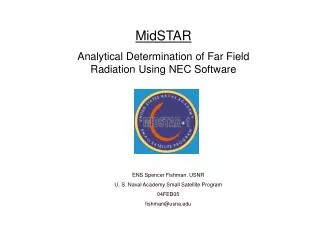
MidSTAR Analytical Determination of Far Field Radiation Using NEC Software. ENS Spencer Fishman, USNR U. S. Naval Academy Small Satellite Program 04FEB05 fishman@usna.edu. Y. Isometric View. Bottom View. X: MidSTAR principle axis Y: Launch vehicle vertical axis Z: Perpendicular to X,Y

E N D
MidSTAR Analytical Determination of Far Field Radiation Using NEC Software ENS Spencer Fishman, USNR U. S. Naval Academy Small Satellite Program 04FEB05 fishman@usna.edu
Y Isometric View Bottom View X: MidSTAR principle axis Y: Launch vehicle vertical axis Z: Perpendicular to X,Y Y’: Transmit antenna axis Main Rx Ant #2 Aux Tx Ant #2 Y Y’ 21.2” Aux Tx Ant #1 Main Rx Ant #1 Z Main Tx Ant #2 30” Coordinate System Aux Rx Ant #2 X Y’ Main Tx Ant #1 Main Rx Ant #2 Aux Rx Ant #1 Main Tx Ant #1 45° Z Lightband X Aux Tx Ant #2 X-Z plane MidSTAR Antenna Layout • Frequencies:Receive: 1.767 GHz, Transmit: 2.2022 GHz • Quarter-wave dipole omni-directional antennas • Antenna lengths: Rx: 4.24 cm, Tx: 3.41 cm • 4 Tx, 4 Rx antennas • Main and auxiliary communications systems each use 2 transmit and 2 receive antennas • Main and auxiliary antennas are not activated simultaneously
0 dBi Peak antenna gain is assumed to be 2.0 dBi (typical for monopoles) Y’ Radiated field is symmetric about Y’ axis
3-D Field Y’ • Approximating Peak EIRP • Total transmitter power is 1 W, split between two antennas (0.5 W each) • Assume peak antenna gain is 2.0 dBi (typical for monopoles) • Neglect losses • EIRPmax = -1.0 dBW • Actual Field Considerations • Line losses • VSWR ~ 1.5:1 • Antennas will not be perfectly resonant • Feed-point impedance • Ground plane will be affected by spacecraft edges and solar panels