SMAW Welding
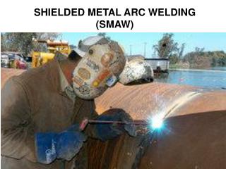
SMAW Welding. Definition. Shield Metal Arc Welding is an arc welding process that uses a consumable electrode to initiate the arc and provide the filler material. Arc Welding Safety. What are the principle hazards associated with SMAW?.

SMAW Welding
E N D
Presentation Transcript
Definition • Shield Metal Arc Welding is an arc welding process that uses a consumable electrode to initiate the arc and provide the filler material.
Arc Welding Safety • What are the principle hazards associated with SMAW? What can be done to manage the hazards associated with SMAW?
SMAW Process • The arc temperature over 9,000 oF melts the base metal, the wire core and the coating on the electrode. • The high temperature causes some of the ingredients in the flux to form a gaseous shield. • The electric energy is provided by a power source. • As the weld cools slag forms on top of the weld puddle. What’s the purpose of slag?
Equipment Polarity switch Power cord Electrode holder Electrode Base metal Ground clamp Electrode lead Ground lead Amperage scale Amperage adjustment On/Off switch Welder case
Six (6) Common SMAW Power Supplies What welding current is available from each of these power supplies?
Initiating The Arc • List the six (6) steps for initiating the arc.
Brushing Method • Hold end of electrode about 1/4 - 1/2 inch above the surface. • Lower helmet • Gently brush surface of the metal with the end of the electrode. • When arc starts, lift electrode 1/8 inch. • If electrode sticks, twist it back and forth. If it does not break loose, release electrode from electrode holder. • Do not shut off the welder with the electrode stuck to the metal. Why?
Tapping Method • Set up welder • Hold the electrode at the travel angle and 1/4 - 1/2 inch above the metal. • Quickly lower the electrode until it touches the metal and then lift it 1/8 inch.
Five (5) Factors Controlling the Quality of SMAW Welds • Heat • Electrode • Electrode angle • Arc length • Speed of travel
Five (5) Factors1.Heat • The arc welder must produce sufficient heat (BTU’s) to melt the electrode and the base metal to the desired depth. How is the amount of heat at the weld controlled? What factors determine the amount of heat required for a weld?
Five (5) Factors1.Heat – cont. • What are the characteristics of excessive heat when completing a SMAW joint? What are the characteristics of insufficient heat when completing a SMAW weld?
Five (5) Factors2.Electrodes • What are the two (2) primary requirements for an SMAW electrode? What metals can be welding with the SMAW process? How are SMAW electrodes classified?
American Welding Society (AWS) Classification System • The AWS system designates: • tensile strength, • weld position • coating (flux) • current. The primary difference in the performance of electrodes is the flux.
Arc Welding Electrode Flux • Flux: A material used during arc welding, brazing or braze welding to clean the surfaces of the joint chemically, to prevent atmospheric oxidation and to reduce impurities and/or float them to the surface. (British Standard 499) SMAW fluxes are naturally occurring minerals. The quality, and cost, of the flux is directly related to the amount of resources the manufacture invests purifying the minerals for the flux.
Seven (7) Classifications of Flux constituents calcium, manganese, calcium fluoride and cellulose • Protection from atmospheric contamination & slag formers • Fluxing agents • Arc initiators and stabilizers • Deoxidizes • Physical properties of the flux • Fillers and metallic additions • Binders and flux strength improvers calcium carbonates, rutile, silica, talc nickel and iron powders, sodium, feldspar, clay, talc ferroalloys, ferrosilicon, iron powder manganese, iron, rutile, alumina, silica, calcium fluoride waterglass, mica organic binders ferrow alloys, iron and nickel powders
Electrode Performance Groups • Fast-freeze • Mild steel • Quick solidification of weld pool • Deep penetrating • Recommended for out of position welds • Deep penetrating arc • Fast-fill • Highest deposition rate • Stable arc • Thick flux • Flat position and horizontal laps only • Fill-freeze • General purpose electrodes • Characteristics of fast-freeze and fast-fill • Low hydrogen • Welding characteristics of fill-freeze • Designed for medium carbon and alloy steels
Selecting Electrode Size • What factors determine the optimum diameter of electrode that should be used? Is it permissible to use more than one diameter of electrode to complete a joint? Yes Explain! ROT: the diameter of the electrode should not exceed the thickness of the metal.
Electrode Storage • Electrodes are damaged by rough treatment, temperature extremes and moisture. • The should be kept in their original container until used. • They should be stored in a heated cabinet that maintains them at a constant temperature. • The storage of low hydrogen electrodes is very critical. • Designed to reduce underbead cracking in alloy and medium carbon steels by reducing the the amount of hydrogen in the weld pool. • The flux is hydroscopic-- • Moisture in the flux also causes excessive gasses to develop in the weld pool and causes a defect in the weld called worm holes. What is the primary source of hydrogen in the weld pool? What does that mean?
Five (5) Factors3.Electrode Angle • Two angles are important: • Travel • Work The travel angle is the angle of the electrode parallel to the joint. • The correct travel angle must be used for each joint. • Beads = 15o from vertical or 75o from the work. • Butt joint = 15o from vertical or 75o from the work. • Lap joint = 45o. • T joint = 45o. • Corner = 15o from vertical or 75o from the work. What is the effect of incorrect travel angle?
Five (5) FactorsElectrode Angle-cont. • The work angle is the angle of the electrode perpendicular to the joint. • The appropriate angle must be used for each joint. • Beads = 90o • Butt joint = 90o • Lap joint = 45o • T joint = 45o • Corner = 90o • Can you think of a situation where the travel angle should be modified? • When completing a joint with metal of different thickness.
Five (5) Factors4.Arc Length • The arc length is the distance from the metal part of the electrode to the weld puddle. • The best arc length is not a fixed distance, but should be approximately equal to the diameter of the electrode. What are the characteristics of a weld completed with excessive arc length? What are the characteristics of a weld completed with insufficient arc length?
Five (5) Factors5. Speed of Travel • The speed of travel is measured in inches per minute. What factors determine the best speed of travel?
Five (5) Factors5. Speed-cont. • The ideal speed can be calculated using the volume of the joint and the deposition rate of the electrode. Step one: determine the area of the weld. (Assuming 1/16 inch penetration.) • Step Two: knowing the deposition rate of the electrode, determine the welding speed. (Deposition rate = 2.5 in3/min.)
Five (5) Factors5. Speed-cont. • The correct welding speed is indicated by the shape of the ripples. Too slow = excessive width, excessive penetration Too fast = narrower width, elongated ripple pattern, shallow penetration. Recommended = width 2-3 times diameter of electrode, uniform ripple pattern, full penetration.
Square Groove • A butt joint can be completed with a groove welded on metal up to 1/8 inch thick with a single pass on one side, with no root opening. • Electrode manipulation should only be used to prevent burning through.
Square Groove Thicker Metal • A groove weld on metal up to 1/4 inch thick can be welded with a single pass on one side but, if possible, it should be completed with a single pass on both sides. • Metal this thick requires a root opening to achieve adequate penetration. • Electrode manipulation will reduce penetration.
Single V Groove Weld • Butt joints on metal greater than 1/4 inch thick require joint preparation. • Note that the groove does not extend all the way. A short distance, called the root face, is left undisturbed. • Several different combinations of passes can be used to complete this joint. What determines that amount of joint preparation that must be done before welding? Note: this is the principle use of pattern beads.
Information • In a T-joint the two welding surfaces are at an angle close to 90 degrees from each other. • The welding side and number of passes uses depends on the thickness of the metal, the welding access and capacity of the power supply. • Common joints include. • Plane T • T with joint gap • Single preparation • Double preparation
Plane T-Joint • The plane T joint is very useful for thin metal. • Can be completed at angles other than 90 degrees. • Can be completed with metal of different thickness. • The work angle must be changed to direct more heat to the thicker piece.
T-joint--Thicker Metal • When the metal thickness exceeds 1/8 inch the recommendation is to gap the joint. • Improves penetration • May not be necessary if larger diameter electrode is used and sufficient amperage is available. • The need for a joint gap varies with the type of electrode, but should not exceed 1/8 inch.
T-joint Single Single Bevel • As with other joints, thicker metal must have joint preparation to achieve full penetration with smaller diameter electrodes. • Several different preparations can be used. A popular one is the bevel. • A bevel can be completed by grinding or cutting. • The bevel joint can be completed with electrode manipulation or no electrode manipulation. • When when electrode manipulation is used to fill the joint, the first pass should be a straight bead with no manipulation.
T-joint Double Bevel • The double bevel T-joint is recommended for metal 1/2 inch thick and thicker. • The root passes should be with not manipulation, but the filler passes can be completed with either straight beads or patterns beads. • Alternating sides reduces distortion.
Common SMAW Defects Under Cutting Porosity • Undercutting • improper welding parameters; particularly the travel speed and arc voltage. • Porosity • Atmospheric contamination or excess gas in the weld pool. Hot Cracks Slag Inclusions • Hot cracks • Caused by excessive contraction of the metal as it cools. • Excessive bead size • May also be found at the root of the weld. • Slag inclusions • Long arc • Incomplete removal of slag on multipass welds.
SMAW Weld Defects-cont. Incomplete fusion Toe cracks Microcracks Underbead cracks • Toe Cracks • Excessive heat and rapid cooling. • Underbead cracks • Excessive hydrogen in weld pool • Microcracks • Caused by stresses as weld cools. • Incomplete fusion • Incorrect welding parameters or welding techniques.