Status of the sensor development for future Super-Colliders
450 likes | 601 Vues
Status of the sensor development for future Super-Colliders. G. Casse. Outline. Requirements for detectors for future supercolliders Vertex and tracker sensors Definition of the challenges: speed and radiation hardness Status Conclusions. 2. Possible 20 Year LHC Schedule. Comments:

Status of the sensor development for future Super-Colliders
E N D
Presentation Transcript
Status of the sensor development for future Super-Colliders G. Casse
Outline • Requirements for detectors for future supercolliders • Vertex and tracker sensors • Definition of the challenges: speed and radiation hardness • Status • Conclusions 2
Possible 20 Year LHC Schedule • Comments: • Remember the Tevatron at Fermilab started operating at 3.5× the SPS (CERN) collider energy in October 1985 and only finally shut down this September after 25 years at the energy frontier • The initial design luminosity of the Tevatron was 1030cm−2s−1, however the accelerator has been continually upgraded over the years and was finally able to deliver luminosities up to 4 × 1032cm−2s−1
Phase-0 (installation 2013-14) • New Aluminum beam pipes to prevent activation problem and reduce BG • New Insertable pixel B-Layer (IBL) (drives shutdown schedule) • New pixel services (nSQP) ( pending decision by mid 2012) • New small Be pipe • New evaporative cooling plant for Pixel and SCT + IBL CO2 cooling plant • Replace all calorimeter Low Voltage Power Supplies • Finish the installation of the EE muon chambers staged in 2003 + additional chambers in the feet (new electronics) and elevators region • Exchange all broken TGCs where possible • Consolidate part of the LUCID system • Upgrade the magnets cryogenics with a new spare main compressor and decouple toroid and solenoid cryogenics • Add specific neutron shielding ( behind end-cap toroid, USA15) • Revisit the entire electricity supply network (UPS,…) • Repairs and maintenance work in general !!! • Preparations for Phase I upgrade (moveable b-pipe, AFP prototypes,… ) • MBTS removal and possible replacement
Phase-I (installation in or before LS2) • New muon small wheels with more trigger granularity and trigger track vector information • Fast track trigger (FTK) using SCT and pixel hits (input to LVL2) expected installation before LS2 • Higher-granularity calorimeter LVL1 trigger and associated front-end electronics • Topological trigger processors combining LVL1 information from different regions of interest (improvements starting well before LS2) • Adapt central LVL1 trigger electronics to new needs • New diffractive physics programme detector stations planned at ~210 m (full 3D edgeless and timing detectors, to start taking data before LS2) • New Tiles crack-gap scintillators and some new trigger electronics • Adapt if proven necessary HLT hardware (in particular network) to the new needs/conditions
Phase-II (installation 2022-23) • New Inner Detector (strips and pixels) − very substantial progress in many R&D areas • New LAr front-end and back-end electronics • New Tiles front-end and back-end electronics • TDAQ upgrade • TAS and shielding upgrade • Various infrastructure upgrades • Common activities (installation, safety, …) • New FCAL ? • Lar cold electronics consolidation ? • L1 track trigger (possible role of gas detectors) ? • Muon Barrel and Large Wheel system upgrade ? • LUCID upgrade ?
Finally look to double the energy (HE-LHC) 16.5+16.5 TeV proton collider in the LHC tunnel Integrated luminosity: 200 fb-1 to 300 fb-1 per year Leveled peak luminosity: L = 5 ×1034 cm-2 sec-1 Total integrated luminosity: Virtual peak luminosity: L = 10 ×1034 cm-2 sec-1 HL-LHC Performance Goals w/o luminosity leveling 10-35 with luminosity leveling 5.10-34 : ca. 3000 fb-1 Oliver Brüning BE-ABP LHCC meeting, CERN, 14 June 2011 7
Upgrading the General Purpose Detectors • To keep ATLAS and CMS running beyond ~10 years requires tracker replacement • Current trackers designed to survive up to 10Mrad in strip detectors ( ≤700 fb-1) • For the luminosity-upgrade the new trackers will have to cope with: • much higher integrated doses • (need to plan for 3000fb-1) • much higher occupancy levels (up • to 200 collisions per beam crossing) • Installation inside an existing • 4π coverage experiment • Budgets are likely to be such that replacement trackers, while needing higher performance to cope with the extreme environment, cannot cost more than the ones they replace • To complete a new tracker for ~2020, require Technical Design Reports by 2014/15 • (Note the ATLAS Tracker TDR: April 1997; CMS Tracker TDR: April 1998)
Draft Target Specifications Plan for occupancy numbers based on this (see µ values below) Plan integrated dose figures based on this µ values going with the peak luminosity figure if achieved with 25ns beam crossing When we calculate the dose figures which are used to specify the radiation hardness of components which can be reliably tested for post-irradiation performance (eg ASICs, silicon sensors, diamond, ...) apply this safety factor to the dose calculations in setting the radiation survival specification (Still under discussion)
Radiation Background Simulation At inner pixel radii - target survival to 2-3×10¹⁶ neq/cm2 For strips 3000fb-1 ×2 implies survival required up to ~1.3×10¹⁵ neq/cm2 I. Dawson et al.
Dominated by pion damage Dominated by neutron damage Radiation levels expected with sLHC • Radiation hardness requirements (including safety factor of 2) • 2 × 10¹⁶ neq/cm2 for the innermost pixel layers • 1× 10¹⁵ neq/cm2 for the innermost strip layers [M.Moll]
Status of radiation hardness studies • Crucial point for Vertex and Tracker sensors • Silicon still the forefront runner, no serious possibility to change track within the timescale (possible exception, diamond for innermost layer....). • Dedicated R&D activity within the upgrading experiments and a dedicated community (CERN-RD50). Most advanced results from this community.
Development of Radiation Hard Semiconductor Devices for High Luminosity Colliders Membership changes in 2010:- left RD50: Lancaster University (UK) (Teamleader A.Chilingarov ) - joined RD50: Institut de Física d'Altes Energies (IFAE), Bellaterra (Barcelona), Spain (Teamleader S.Grinstein) Instituto de Física de Cantabria (IFCA), Santander, Spain (Teamleader Ivan Vila) 255 Members from 48 Institutes 39 European and Asian institutesBelarus (Minsk), Belgium (Louvain), Czech Republic (Prague (3x)), Finland (Helsinki, Lappeenranta), Germany (Dortmund, Erfurt, Freiburg, Hamburg, Karlsruhe, Munich), Italy (Bari, Florence, Padova, Perugia, Pisa, Trento), Lithuania (Vilnius), Netherlands (NIKHEF), Norway (Oslo (2x)), Poland (Warsaw(2x)), Romania (Bucharest (2x)),Russia (Moscow, St.Petersburg), Slovenia (Ljubljana), Spain (Barcelona (2x), Santander, Valencia), Switzerland (CERN, PSI), Ukraine (Kiev), UnitedKingdom (Glasgow, Liverpool) 8 North-American institutesCanada (Montreal), USA (BNL, Fermilab, New Mexico, Purdue, Rochester, Santa Cruz, Syracuse) 1 Middle East instituteIsrael (Tel Aviv) Detailed member list: http://cern.ch/rd50
Defect Characterization • WODEAN project (initiated in 2006, 10 RD50 institutes, guided by G.Lindstroem, Hamburg) • Aim: Identify defects responsible for Trapping, Leakage Current, Change of Neff • Method: Defect Analysis on identical samples performed with the various tools available inside the RD50 network: • C-DLTS(Capacitance Deep Level Transient Spectroscopy) • I-DLTS (Current Deep Level Transient Spectroscopy) • TSC (Thermally Stimulated Currents) • PITS(Photo Induced Transient Spectroscopy) • FTIR(Fourier Transform Infrared Spectroscopy) • RL(Recombination Lifetime Measurements) • PC(Photo Conductivity Measurements) • EPR(Electron Paramagnetic Resonance) • TCT(Transient Charge Technique) • CV/IV • ~ 240 samples irradiated with protons and neutrons • first results presented on 2007 RD50 Workshops,further analyses in 2008 and publication of most important results in in Applied Physics Letters… significant impact of RD50 results on silicon solid state physics – defect identification Example: TSC measurement on defects (acceptors) responsible for the reverse annealing
Sample Fluence [cm-2] [V20] [cm-3] Introduction rate[cm-1] [V2-] [cm-3] Introduction rate [cm-1] FZ 1*1016 3.7*1015 0.37 1.3*1015 0.13 MCz 1*1016 3.39*1015 0.34 - - FZ 3*1016 9.7*1015 0.32 - - MCz 3*1016 9.1*1015 0.30 3.8*1015 0.13 Infrared absorption (FTIR) • IR absorption measurements allow to measure defect concentrations after very high fluences • Example: IR absorption measurements after neutron irradiation (3×10¹⁶ n/cm2) • Same Vacancy concentration in CZ and FZ silicon. RT Illuminationat low T (8K) V2- V20 14K • Remaining question: Are the vacancies inside the defect clusters (disordered regions) charged differently than outside the clusters? Needs: Electron Irradiation to clarify.
Summary – defects with strong impact on the device properties at operating temperature Point defects EiBD = Ec – 0.225 eV nBD =2.310-14 cm2 EiI = Ec – 0.545 eV nI =2.310-14 cm2 pI =2.310-14 cm2 Cluster related centers Ei116K = Ev + 0.33eV p116K =410-14 cm2 Ei140K = Ev + 0.36eV p140K =2.510-15 cm2 Ei152K = Ev + 0.42eV p152K =2.310-14 cm2 Ei30K = Ec - 0.1eV n30K =2.310-14 cm2 0 charged at RT +/- charged at RT E30K 0/+ P0/+ VO -/0 BD 0/++ V2 -/0 Ip0/- H152K 0/- H140K0/- H116K0/- CiOi+/0 B 0/- extended defects Point defects
Summary – defects with strong impact on the device properties at operating temperature Point defects EiBD = Ec – 0.225 eV nBD =2.310-14 cm2 EiI = Ec – 0.545 eV nI =2.310-14 cm2 pI =2.310-14 cm2 Cluster related centers Ei116K = Ev + 0.33eV p116K =410-14 cm2 Ei140K = Ev + 0.36eV p140K =2.510-15 cm2 Ei152K = Ev + 0.42eV p152K =2.310-14 cm2 Ei30K = Ec - 0.1eV n30K =2.310-14 cm2 0 charged at RT +/- charged at RT E30K 0/+ P0/+ VO -/0 BD 0/++ V2 -/0 Ip0/- H152K 0/- H140K0/- H116K0/- CiOi+/0 B 0/- extended defects Point defects positive charge (higher introduction after proton irradiation than after neutron irradiation) positive charge (high concentration in oxygen rich material) leakage current+ neg. charge(current after irradiation) Reverse annealing(neg. charge)
Radiation tolerance prediction: “old” method “Good” operation of sensors was based on the ability to provide a bias voltage corresponding to 120-130% of the full depletion voltage. But the VFD would be well over 10000V at HL-LHC doses ....
More relevant method: analogue readout with LHC speed electronics Mip signal from 90Sr source Analogue information from the Alibava board (equipped with Beetle chip)
RD50: Device engineeringp-in-n versus n-in-p (or n-in-n) detectors p-type silicon after high fluences:(still p-type) n-type silicon after high fluences:(type inverted) n+on-p p+on-n • n-on-p silicon, under-depleted: • Limited loss in CCE • Less degradation with under-depletion • Collect electrons (3 x faster than holes) • p-on-n silicon, under-depleted: • Charge spread – degraded resolution • Charge loss – reduced CCE Comments:- Instead of n-on-p also n-on-n devices could be used
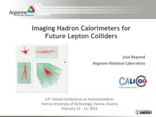
The readout side yields remarkable improvement. Comparison of n-in-p µ-strip sensor (irradiated to 4E14 neq cm-2) and p-in-n (irradiated to 3E14 neq cm-2). G. Casse et al., 2000
N-side read-out can make planar segmented Si detectors suitable for tracking in extreme (SLHC levels: 1-2x1016 cm-2) radiation environments. Schematic changes of Electric field after irradiation Effect of trapping on the Charge Collection Efficiency (CCE) Qtc Q0exp(-tc/ttr), 1/ttr = bF. Collecting electrons provide a sensitive advantage with respect to holes due to a much shorter tc. P-type detectors are the most natural solution for e collection on the segmented side. N-side read out to keep lower tc
Effect of trapping on the Charge Collection Distance Qtc Q0exp(-tc/ttr), 1/ttr = bF. vsat,e x ttr = lav be = 4.2E-16 cm-2/ns G. Kramberger et al., NIMA 476(2002), 645-651. After heavy irradiation the charge collection distance (CCD) of thin detectors should have a similar (better?) charge collection efficiency (CCE) as thicker ones. bh = 6.1E-16 cm-2/ns lMax,n (F=1e14) 2400µm lMax,n (F=1e16) 24µm lMax,p (F=1e14) 1600µm lMax,p (F=1e16) 16µm The reverse current is proportional to the depleted volume in irradiated detectors. Do thin sensors offer an advantage in term of reduced reverse current compared to thicker ones (this aspect is particularly important for the inner layer detectors of SLHC, where significant contribution to power consuption is expected from the sensors themselves)?
Results with proton irradiated 300 mm n-in-p Micron sensors (up to 1x10¹⁶ neq cm-2) Irradiated with reactor neutrons RED: irradiated with 24GeV/c protons Other: 26MeV protons
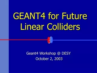
... but there is dependence on the thickness: 140 and 300 mm n-in-p Micron sensors Cold(0-5 oC) irradiation to 1x10¹⁶ neq cm-2 with 24 GeV/c protons Irradiation to 1x10¹⁶ neq cm-2 with 26 MeV protons Irradiation to 2x10¹⁶ neq cm-2 with reactor neutrons G. Casse, VERTEX 2010, 6-11 June 2010
The results in the previous slide are a compilation of results obtained by Liverpool. Results from the JSI of Ljubljana show very good agreement with the neutron irradiations. Here they have been pushed to higher voltages and they show a collected charge equal to the charge collected by non-irradiated sensors after heavy irradiation. I. Mandic at the 12th RD50 workshop. Liverpool
140 and 300 mm n-in-p Micron sensors after 5x10¹⁵ neq 26MeV p Evidence of a charge multiplication effect: not only the whole charge is recovered, but increased by f = 1.75 Also CM in diodes (J. Lange, 15th RD50 workshop).
TCAD, M. Benoit et al., presented at the ATLAS Upgrade meeting, DESY, Hamburg, 19/04/2010 Radiation damage G. Casse, VERTEX 2010, 6-11 June 2010
ISE TCAD, M. Benoit et al., presented at the ATLAS Upgrade meeting, DESY, Hamburg, 19/04/2010 140mm 300mm G. Casse, VERTEX 2010, 6-11 June 2010
“Edge-TCT” a new way of using TCT Illumination close to strips – hole injection IR laser active volume The idea is to use focused IR laser to simulate grazing technique: Advantages: • Position of e-h generation can be controlled by moving tables • the amount of injected e-h pairs can be controlled by tuning the laser power • easier mounting and handling • not only charge but also induced current is measured – a lot more information is obtained Drawbacks: • Applicable only for strip/pixel detectors if 1060 nm laser is used (light must penetrate guard ring region) • Only the position perpendicular to strips can be used due to widening of the beam! Beam is “tuned” for a particular strip • Absorption falls with temperature of the sensor – a relatively powerful laser is required for large signal and makes absolute measurements of the charge more difficult • Light injection side has to be polished to have a good focus – depth resolution • It is not possible to study charge sharing due to illumination of all strips The same amount of charge injected for close to strip and close to backplane – change of e-h fraction scan direction y (p) Illumination close to backplane – hole injection bias G. Kramberger et al.,"Edge TCT, A new way of extracting electric field from irradiated silicon detectors", 13th RD50 Workshop, Freiburg, 3-5.6.2009
CM is a well documented effect, but we are not mastering it yet We can qualitatively understand it. We are investigating it from various perspectives. ISE TCAD, M. Benoit et al., presented at the ATLAS Upgrade meeting, DESY, Hamburg, 19/04/2010 TCT studies 2nd peak due to avalanche multiplication the difference in peak amplitude for different y is due to electrons trapped G. Kramberger wt al., 18th RD50 workshop.
Consistent results from various manufacturers 500 V e2vPreliminary e2v Preliminary 900 V
Cluster sizes after various doses Seed cut = 3.5*ENC Cluster = 2.5*ENC G. Casse, NSS-2011, 23-28 October 2011, Valencia
Cluster sizes after various doses G. Casse, NSS-2011, 23-28 October 2011, Valencia
Cluster sizes after various doses G. Casse, NSS-2011, 23-28 October 2011, Valencia
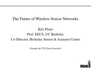
Changes of cluster size with dose 700 V 500 V 900 V 1100 V
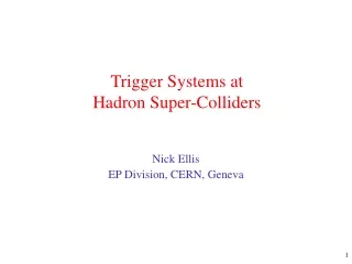
Leakage current, -10ºC, 1016 neq/cm2 Charge multiplication Annealing time Alternative Technologies to Planar Silicon 3D Sensors with Doped Through Silicon Columns Planar CVD Diamond: Poly-crystalline or Single Crystal Diamond Vbias fixed at 150V Trap-to-band tunnelling Impact ionisation Marko Mikuž: Small radius pixel sensors
Current ATLAS SCT Module Designs ATLAS Tracker Based on Barrel and Disc Supports Effectively two styles of double-sided modules (12cm long) each sensor ~6cm wide (768 strips of 80μm pitch per side) Hybrid cards carrying read- out chips and multilayer interconnect circuit Sensor Sensor Sensor Sensor Barrel Modules Forward Modules (Hybrid bridge above sensors) (Hybrid at module end)
Stave Prototypes and Powering Concepts Concept based on single-sided modules sandwiched around a carbon fibre core with integrated cooling and bus-tape (more similar to current pixels) tested 2.5V 12.5V 0V 5V 7.5V 10V Targets low mass and large-scale production Full Length 12 Module Mock-up Stave Glue Glue 9 .75cm 4 module fully working SP stave built and tested Serial Powered Chain of Hybrids Liverpool Hybrid and Module Design H0 H1 H2 H3 DC-DC Stavelet (CF core made at Liverpool) Both powering schemes can be made to work in this configuration
ATLAS Large Area Strip Sensors • Collaboration of ATLAS with Hamamatsu Photonics (HPK) to develop 9.75x9.75 cm2 n+-strip in p-type substrate devices (6 inch wafers) for strip regions • 4 segments (2 axial, 2 stereo), 1280 strip each, 2.45cm long, 74.5 mm pitch, ~320 mm thick • FZ1 <100> and FZ2 <100> material studied • Miniature sensors (1x1 cm2) for irradiation studies Axial Stereo • >150 full-size sensor prototypes delivered and characterized to final specifications • Inter-strip capacitance & resistance, coupling capacitance, depletion voltage, leakage currents and polysilicon resistors qualified Use of p-type silicon for high radiation environments pioneered by Liverpool with Micron Semiconductor (UK) Ltd and CNM Barcelona
Module Assembly Progress Tooling for all sites designed by and provided from Liverpool
Stavelet Construction – Electrical Module Programme -25°C -32°C -25°C
Conclusions The progress of Si sensor technology make possible to equip the future HL colliders with efficient sensors (to 3000 fb-1) to the innermost layers. Still a big challenge are services (cooling, powering .....) and cost.......