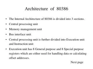
80386 MICROPROCESSOR Architecture
Microprocessor Architecture. UOP S.E.Comp (Sem-I). 80386 MICROPROCESSOR Architecture. Prof.P.C.Patil Department of Computer Engg Matoshri College of Engg.Nasik pcpatil18@gmail.com. Block Diagram. Pin Discription. Pin Discription. These signals are separated in four major groups :

80386 MICROPROCESSOR Architecture
E N D
Presentation Transcript
Microprocessor Architecture UOP S.E.Comp (Sem-I) • 80386 MICROPROCESSOR • Architecture Prof.P.C.Patil Department of Computer Engg Matoshri College of Engg.Nasik pcpatil18@gmail.com.
Pin Discription • These signals are separated in four major groups : • Memory/IO interface • Interrupt interface • DMA interface • Coprocessor interface
Pin Discription • Memory/IO lnterface • Data Bus : • The data bus consists of 32 pins (D31 – D0). These lines are used to transfer 8, t6, 24, or 32-bit data at one time. • Address Bus : • The B0386DX generates 32-bit address. • The higher 30-bits of address are sent on the A31-A2. • The lower 2-bits, select one of four bytes of the 32-bit data bus. • These two bits are intemally decoded and sent on the four byte enable pins ( BE3- BE0)
Pin Discription • Bus Status Signals : • The bus status signals decide the type of bus cycle to be performed. These signals are : 1. Address status 2. Write/Read 3. Memory/IO 4. Data/Control 5. LOCK
Pin Discription • Bus Status Signals : • The bus status signals decide the type of bus cycle to be performed. These signals are : 1. Address status 2. Write/Read 3. Memory/IO 4. Data/Control 5. LOCK
General Purpose Register • The 80386 contains 32-bit general purpose register called EAX, EBX, ECX, EDx, ESP,EBP, ESI, and EDI. • The lower 16-bits of each of the general purpose register can be accessed individually. • These 16-bit registers are accessed as AX, BX, CX, DX, SP, Bp, SI, and, DI respectively. • The AX, BX, CX and DX registers can be further divided into fwo separate bytes : Higher byte and lower byte.
Segment Register • The 80386 has a 1 MB address space in real mode. • But all of this memory cannot be active at one time. • It supports six simultaneously accessible memory blocks called segments. • A segment represents an independently accessible block of memory consisting of 64 K consecutive byte-wide storage locations. • These segments are addressed by 16-bit registers : CS, DS, ES, SS, FS and CS.
Segment Register • CS (Code Segment) : holds the base address of the currently active code segment. • DS (Data Segment) : is used to hold the address of currently active data segment. • ES (Extra Segment), FS, and GS are used as general data segment registers. • These registers hold the base addresses of three different memory segments. • These segments are referred as to Extra Segments. • The base address of the currently active. stack segment is contained in the SS (Stack Segment) register.
Flag Register • Status Flags • CF (Carry Flag) • PF (Parity Flag ) • AF (Auxiliary Carry Flag) • ZF (Zero Flag) • SF (Sign Flag) • OF (Overflow Flag) • Control Flags • DF ( Direction flag) • System Flags • VM (Virtual Memory) flag • R (Resume) flag • NT (Nested flag) • IOPL (l/O Privilege level) • lF (lnterrupt Flag) • TF (Trap Flag)
Flag Register • VM (Virtual Memory) flag : • Indicates operating mode of 80386. • When VM flag is set, 80386 switches from protected mode to virtual 8086 mode. • R (Resume) flag : • This flag, when set allows selective masking of some exceptions at the time of debugging. • NT (Nested flag) : • This flag is set when one system task invokes another task.(i.e. nested task). • IOPL (l/O Privilege level) : • The two bits in the IOPL are used by the processor and the operating system to determine your application's access to I/O facilities.
Flag Register • lF (lnterrupt Flag) : • When interrupt flag is set, the 80386 recognizes and handles external hardware interrupts on its INTR pin. • If the interrupt flag is cleared, 80386 ignores any inputs on this pin. • The IF flag is set and cleared with the STI and CLI istructions, respectively. • TF (Trap Flag) : • Trap flag allows user to single-step through programs. An 80386 detects that this flag is set, it executes one instruction and then automatically generates an internal exception 1. • After servicing the exception, the processor executes next instruction and repeats the process. • This single stepping continues until prgram code resets this flag for debugging programs single step facility is used.
System Adderss Register • There are four system address register : • TR (Task Register) • IDTR (Interrupt Descriptor Table Register) • GDTR (Global Descriptor Table i.egrster) • LDTR (Local Descriptor table Register). • These registers hold the addresses for the four special descriptor table segments.
System Adderss Register • TR (Task Register) • Points to the Task state segment • IDTR (Interrupt Descriptor Table Register) • points to the Interrupt Descriptor table (IDT) • The GDTR (Global Descriptor Table Register) • points to the Gtobal Descriptor Table (GDT) • LDTR (Local Descriptor Table Register) • points to the Local Descriptor Table (LDT)
Control Register • There are four control registers : • CR0, CR1, CR2 and CR3. • These registers define the machine state that affects all the tasks in the systems.
Control Register • CR0 : Holds the MSW (Machine Status Word). • It contains six status bits : • PE (Protection Enable) • MP (Math Present) • EM (Emulate Coprocessor) • TS (Task Switched) • ET (Extension Type) • PG (Paging).
Control Register • PE (Protection Enable) : • This bit is similar to the VM bit in EFLAGs in that it controls the 80386's mode of operation. • When PE is set, it is in protection mode otherwise it operates in Real Mode. • MP (Math Present) : • When this bit is set, the 80386 assumes that real floating point hardware (80287 or 80387) is present in the system. • When this bit is clear, the 80386 assumes that no such coprocessor exists, and will not attempt to use real floating point hardware. • EM (Emulate coprocessor) : • When this bit is set, the 80386 will generate an exception 11 (device not available) whenever it attempts to execute a floating point instruction. • Programmer can use this exception handler to emulate floating point hardware in software.
Control Register • TS (Task Switched) : • The 80386 sets the bit automatically every time it performs a task switch. • It will never clear this bit on its own. But programmer can clear this bit using CLTS instruction. • ET (Extension Type) : • When power is applied, 80386 detects whether numeric Processor connected is 80282 or 80387 and sets ET to logic 1, if numeric processor is 80387. • This is necessary because the 80387 uses a slightly different protocol than 80287. • PG (Paging) : • This bit enables or disables paging mechanism in Memory Management Unit (MMU). • If bit is set, paging is enabled.
Control Register • Control Register 1 (CR1) • This is reserved by Intel. • Control Register 2 (CR2) • CR2 is read-only register. The 80386, itself writes the last 32-bit linear address of page fault routine in this register. When page fault occurs, the 80386 generates exception 14 (page fault) • This address is important for writing page fault routine. • The page fault routine helps programmer to find cause of the fault. • Control Register 3 (CR3) • Control register 3 holds the physical address of the root of the two level paging tables used when paging is enabled. It is also called Page Directory Base Register
Physical Address Space • The physical memory of an 80386 system is organized as a sequence of 8-bit bytes. • Each byte is assigned a unique address that ranges from zero to a maximum of 2(32) – 1 (4 gigabytes). • 80386 programs/ however, are independent of the physical address space. • This means that programs can be written without knowledge of how much physical memory is available and without knowledge of exactly where in physical memory the instructions and data are located. • The model of memory organizatton seen by applications programmers is determined by systems-software designers. • The architecture of the 80385 gives designers the freedom to choose a model for each task.
Physical Address Space • The model of memory organization can range between the following extremes: • Flat address space : • In a "flat" model cf memory organization, the applications programmer sees a single aray of up to 2(32) bytes ( 4 gigabytes). • The processor maps the 4 gigabyte flat space onto the physical address space by the address translation mechanisms.
Physical Address Space • Segmented address space : • A segmented model consisting of a collection of up to 16,383 linear address spaces of up to 4 gigabytes each. • In a segmented model of memory organization, the address space as viewed by an applications program (called the logical address space) is a much larger space of up to 2(46) byte (64 terabytes). • The processor maps the 64 terabyte logical address space onto the physical address space (up to 4 gigabytes) by the address translation mechanisms. • Both models can provide memory protection. Different tasks may employ different models of memory organization.
Data Types • Data types supported by 80386 DX