Advanced CO2 Cooling Systems for the CBM Silicon Tracking System in Particle Detectors
This work focuses on the TRACI-XL cooling system utilizing CO2 as a refrigerant for the CBM Silicon Tracking System. CO2 offers superior thermodynamic properties, lower energy consumption, and a reduced carbon footprint, making it ideal for modern particle detectors. The system features smaller piping and components, leading to significant space and cost savings. The TRACI-XL is being upgraded to deliver up to 1 kW cooling power, optimizing heat extraction from read-out electronics. This innovative solution addresses critical cooling needs in high-energy physics experiments.

Advanced CO2 Cooling Systems for the CBM Silicon Tracking System in Particle Detectors
E N D
Presentation Transcript
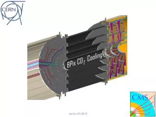
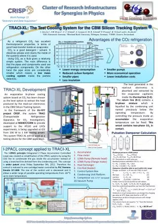
Work Package 13 “Detectors and Data Acquisition” CO Cooling Systems TRACI-XL: The Test Cooling System for the CBM Silicon Tracking System J. Sánchez1, J.M. Heuser1, C. J. Schmidt1,A. Lymanets2,H. R. Schmidt2P. Petagna3, B. Verlaat3and L. Zwalinski3 1GSI, Darmstadt, Germany; 2Eberhard Karls University, Tübingen, Germany; 3CERN, Geneva, Switzerland As a refrigerant CO2 has excellent thermodynamic properties, in terms of good heat-transfer inside an evaporator. CO2 is a good detergent / solvent. It dissolves grease and cleans the inside of the systems where it is used. Using CO2 as a fluid gives a relatively simple system. The main difference is that the pipes and components used are refrigeration components. On the other hand the pipe sizes are considerably smaller which means a low mass cooling system inside the particle detectors. Advantages of the CO2 refrigeration • Lower energy consumption • Reduced carbon footprint • Smaller pipes • Less insulation • Smaller pumps • More economical operation • Lower installation costs The heat generated in the read-out electronics is absorbed and extracted by the evaporator capillaries inside the thermal box (5-6). TRACI-XL Development 2 An evaporative bi-phase cooling system based on CO2 has been chosen as the best option to extract the heat produced by the read-out electronics in the CBM Silicon Tracking System. In the framework of the EU-FP7 project CRISP, the system TRACI (Transportable Refrigeration Apparatus for CO2 Investigation), developed at NIKHEF/CERNto provide support to the ATLAS and LHCbexperiments, is being upgraded at GSI from 100 W to 1 kW cooling power. This system TRACI-XL will be used as a testing device for the CBM application. The return line (8-1) contains a bi-phase mixturewhich is liquefied by the condensing unit named previously below the operating temperature. By controlling the pressure inside an accumulator the evaporation temperature can be fixed. This vessel contains two-phase CO2in contact. 7 4 1 10 5 9 8 6 Pulsation Dampener Calculation 3 --- CO2 (R744)Line --- Rest of the System I-2PACL concept applied to TRACI-XL Accumulator Flow meter LEWA Pump (Remote head) LEWA Pump (Flange motor) Heat Exchanger Fire Rod (heater) Control System Box Condensing Unit Platform Compressor 2DC-3.F1Y Varispeed Vacuum Pump Discharge pressures LEWA pump: Pd,min=22 bar Pd,max=79 bar Pmin=P1=20.9 bar Pmax=P2=82.95 bar Pt≈ theoretical or work pressure. Residual pressure admitted ±5% (by now) P1 = Pt1 - ( 5/100 ) ∙ Pt2 = 20.9 P2 = Pt2 + ( 5/100 ) ∙ Pt1 = 82.95 Dampener should be able to work within this range Plunger: ø=25mm L=15 mm dV=7363.11 mm3 If V1= V0 – v, and v = 0.1 ∙ V0 (1) We have V1= 0.9 ∙ V0 (2) and also V2=V1- dv (3) Therefore P0=0.9xP1 = 18.81 bar (4) Finally from (1) (2) (3) and (4) we will obtain: P0 ∙ V0=P2 ∙ V2 ; 0.9P1∙ V0=P2 (V1-dv) =P2 (0.9V0-dv) from the underlined equalities we have the final formula Ambient or circuit temperature can change the charging gas value at 20⁰C (take note that for a 10⁰C of temperature variation the gas pressure will change approx. a 3%) This volume has to be equal to ”V2” from the formula P2/P0= V0/V2 then: ( V0 / 13.67) = ( 82.95/ 18.81 ) →V0 = 60.28 cm3 The I-2PACL principle (Integrated 2 Phase Accumulator Controlled Loop) was created as simplification of the 2PACL systems by using the CO2 line to condensate the gas inside the accumulator instead of using a branched line derived from the condensing unit. This concept is under patentsince Friday September 9th, 2011. Therefore the control is reduced to one cartridge heater controlled by PLC Siemens SimaticS7-1200. The size of the control unit is decreased and it allows a wider range of possible operating temperatures from -30⁰C up to room temperature. Bitzer 2DC-3.F1Y Varispeed: • at 30 Hz; Q0= 0,55 kW, T0 =-45◦ C, Tsuction = -30◦ C, Tc = +35◦ C, Tsub= 3 K, R404a. • at 87 Hz; Q0 = 1.59 kW, T0 = -45◦ C, Tsuction = -30◦ C, Tc = +35◦ C, Tsub= 3 K, R404a. -45⁰C -40⁰C -30⁰C