Download
1 / 9
90 likes | 218 Vues
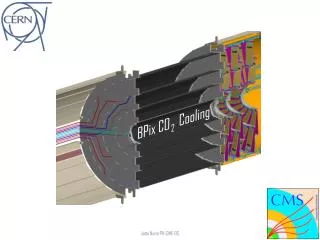
This project focuses on developing a CO2 cooling system for the PIX layer 1 circuit as part of the 2009 Program. The system includes a blow system based on the NIKHEF/CERN design with a cooling power of approximately 144 W, followed by a closed recirculating system designed to provide about 1 kW of cooling power. Key components include a liquid CO2 bottle, mass flow meter, rheonik meter, heat exchanger, and custom-built pressure vessels. The goal is to establish efficient heat transfer mechanisms for testing advanced detector technologies.

E N D
CO2 Cooling Research @ IPNL Nick Lumb, 28/01/09
Programme 2009 • Jan – April: Build blow system based on NIKHEF / CERN design • Cooling power ~144 W (PIX layer 1 circuit) • May – Sept: Build re-circulating system based on VELO design • Cooling power ~1 kW
Blow system – components (1) • Liquid CO2 bottle √ • Air Liquide, 50 l • Mass flow meter √ • Rheonik RHM 015 • Swagelok metering valve √ • To adjust the flow rate • Swagelok proportional relief valve √ • To adjust the back pressure (CO2 temp.) • Heat exchanger • Home built concentric tube, 2.8 m heat exchange length
Blow system – components (2) • Julabo F32-EH chiller / heater √ • To heat CO2 to 30°C before venting • -35 to 150°C • 150W cooling power @ -20°C, 2kW heating power • Re-use in re-circulating system (accumulator) • Test capillary √ • To be provided by Hans • 1.5 mm o.d., 76 micron wall thickness • Contacts for low voltage current source (heating) • Pressure gauges √ • Commercial fridge (isolate test capillary from environment) √ • Temperature sensors + read-out √ • Miscellaneous Swagelok connectors √ • Pipe insulation √
The 2-Phase Accumulator Controlled Loop (2PACL) Long distance P4-5 P7 5 Heat out Heat out Condenser 6 Heat in 4 Heat in 2 3 Heat exchanger 1 2-Phase Accumulator Restrictor Pump Re-circulating system B. Verlaat (NIKHEF)
Main extra items needed beyond blow system • Gear pump • E.g. Gather type 1mx-x/12-11 • Minimum pulsing • Being tested by B. Verlaat • Condenser • Could re-use Louvain 2kW chiller • Re-use blow system heat exchanger? • Or buy one (SWEP B12H/1P-SC-U) • Two-phase accumulator • Re-use Julabo heater / cooler • Need to buy / make pressure vessel • Bart rule of thumb: pressure vessel 1.5 x volume of rest of system
Re-use of concentric tube exchanger • Will blow system exchanger be big enough? • Heat transfer calcs for 2-phase flow not elementary! Excel sheet • For blow system, pipes 12x10 and 6x4, flow rate 1cc/s: can get away with length ~2m • For Louvain chiller: • Flow max. = 35 l/min. C6F14 • Require 1 kW cooling power at CO2 temp. -10°C • Assume chiller operates at -23°C • → Heat exchange length needed ~2.8m • Pressure drop (~2 bar) may be a problem
Conclusion • Starting to build blow system • Hope to have it ready with full temperature read-out by end April • Will then build re-circulating system • Tool for testing heat transfer options for PIX and eventually Si strip tracker