Acceleration gradient limitations in room temperature and superconducting acceleration structures
380 likes | 627 Vues
Acceleration gradient limitations in room temperature and superconducting acceleration structures. Nikolay Solyak Fermilab. RT Breakdown studies in recent years.

Acceleration gradient limitations in room temperature and superconducting acceleration structures
E N D
Presentation Transcript
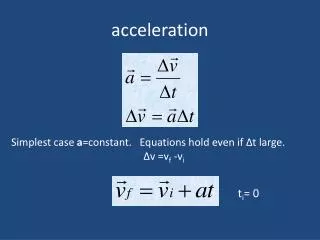
Acceleration gradient limitations in room temperatureand superconducting accelerationstructures Nikolay Solyak Fermilab
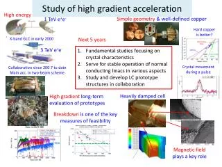
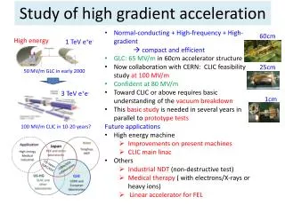
RT Breakdown studies in recent years Aggressive R&D program to understand gradient limitations and physics of breakdown (collaboration of many institutions: SLAC,CERN,KEK,...) • NLC/GLC and CLIC type TW and SW accelerating structures @ 11 GHz (SLAC) and 30 GHz (CERN) • Waveguide, Single cell cavities (SW, TW), • Special cavities (choke-cavity, TM01, PBG) • Frequency dependence • Stored energy, Power and Group velocity • Pulse length dependence • Geometry (low/high impedance structure, slots, choke, phase advance, …) • Materials (Cu, CuZn, Au, Mo, Ti, AL, W, SS, …), coating • Surface preparation, Oxidation • HP processing • Surface and data analysis, Simulations and Theoretical models (field emission models, plasma formation, pulse heating, etc…) Still we have no theory which can explain all data for all set of parameters and make a prediction (example: T53vg3MC (good) T26vg3 (not good))
Test Results at 11 GHz T53VG3MC-11GHz HDS60S power fit = E30
Summary on gradient scaling (CLIC) For a fixed pulse length For a fixed BDR New constrain - modified Poynting vectorwhich is geometry independent and can be scaled among all (TW and SW) Cu structures. • A model of the breakdown trigger based on the pulsed heating of the potential breakdown site by the field emission currents • describes both TW and SW accelerating structure experimental results • Good agreement experiments with analytical estimate A.Grudiev, W.Wuensch
Predictions for test structures Prediction of average unloaded gradient at rect. pulse length of 100ns and BDR=1e-6 based on the results achieved in T53vg3MC: 102.3MV/m at 100ns and BDR=1e-6:Sc=6.2MW/mm2@100ns. Best tested CLIC type structure TD18vg2.4: Eacc ~ 105 MV/m at 100 ns From Alexei Grudiev
“Practical” Gradient limitations in RT accelerating structure • Stored energy (SW), RF power and group velocity (TW) • fraction of energy dissipated in tip vs. geometry? • < 1J energy dissipated in breakdown site • In TWS power absorbed in spot, before plasma built • Breakdown triggered by field emission - Es • Fatigue, modification of boundaries and grains • Magnetic pulse heating – T~ (Hs2)()1/4 (plastic deformation limit: T~50ºC for annealed Cu and ~130ºC) • Possible other limitations (dark current, Multipactoring, couplers, windows, etc…)
Theory of Breakdown • A lot of experimental data is available, more will come soon • Need more statistics for each tested geometry • Few models are presented, but non of them is able to explain all experiments and predict gradient limits • Do we need one theory to explain everything? • Few breakdown mechanisms few theories • Clear criteria to define which mechanism is dominated for chosen parameters space • Facts, which should be explained by theory • Breakdown in TM01 cavity (no surface electric field) • Factor of ~2 difference in electric field in low/ high impedance structures • Gradient limitation in cavity with small gaps (choke cavity) • ….
Scaling results from NC to SC structures • Let’s try to scale gradient limit results obtained for room temperature structures to SC cavity: RT: Eacc~100 MV/m (Epk~200 MV/m) at 100ns. SC: Eacc~ 20 MV/m (Epk~40 MV/m) @ 1ms or Eacc~ 7 MV/m (Epk~14 MV/m) @ 1sec • BDR – usually not considered for SC cavity • Frequency of SC cavity is lower stored energy higher • Conclusion: Physics of breakdown in SRF is different
Achieved Limit of SRF electric field • No known theoretical limit • 1990: Peak surface field ~130 MV/m in CW and 210 MV/m in 1ms pulse. J.Delaen, K.Shepard,”Test a SC rf quadrupole device”, Appl.Phys.Lett,57 (1990) • 2007: Re-entrant cavity: Eacc= 59 MV/m (Epk=125 MV/m,Hs=206.5mT). (R.L. Geng et. al., PAC07_WEPMS006) – World record in accelerating gradient CW 4.2 K EP
“Practical” gradient limitations for SC cavities • Surface magnetic field – 200 mT (absolute limit?) • Field emission, X-ray, starts at ~ 20 MV/m • Thermal breakdown (strong limits for F>2GHz) • Multipactoring (in cavity or couplers) • Medium and high field Q-slopes (cryogenic losses) • Lorentz detuning and microphonics (frequency change) • Quality of surface treatment and Assembly
Limit in gradient and Magnetic field Re-entrant single-cell K. Saito
Pushing up SRF gradient limit New Geometry J.Sekutowicz, V.Shemelin, K.Saito
Traveling Wave Accelerating Structure • ~ 25% (max 42%) higher accelerating gradient (vs. TESLA cavity) • Shorter cells (105 deg phase advance) to improve transit-time factor • No limitation (up to 10m) in cavity length • Need tuning to cancel reflected wave A.Kanareykin, N.Solyak, V.Yakovlev, P.Avrakhov
Field Emission • Caused by macro-particles at the surface • Starts typically >20 MV/m • Exponential Q-drop • X-ray • Dark current • Disappear after HPR • Clean assembly
Thermal breakdown Sub-mm size defects lead to quench Temperature Mapping Particle and hole on thesurface
Large Grain : Hot Spots Large-grain single-cell Hot spots ( large grain cavity ) Reduced after baking Q-slope restored by 40 V anodization G. Ciovati - LINAC (2006)
hk b Thickness Thermal Breakdown in pure Niobium Solution for k=const (thermal conductivity)
Test result of 3.9 GHz accelerating cavity • Final cavity preparation done at FNAL (BCP,HPWR) • Residual resistanceR_res ~ 6 nW • Achieved:H_peak = 103 mT, E_acc = 19 MV/m (Goal: Hpeak= 68 mT, Eacc=14 MV/m) Magnetic field is likely limited by thermal breakdown • No Field Emission • Q ~ 8*10 9 at E_acc =15 MV/m • Maximum accelerating field not depend on Temp 3-cell cavity built at FNAL 9-cell/3.9GHz: Eacc= 21 MV/m TESLA: Eacc= 24 MV/m H = 103 mT No Temperature dependence – why?
1. Non-linear Surface Resistance The non-linear BCS resistance (RF pair breaking) in the clean limit is given by - Linear BCS: Δ~1.5 meV is the superconducting energy gap Where: For 2 cases: β·h<<1 and β·h>>1 it gives: Surface Resistance used in models Non-linear case - blue *P.Bauer et.all, “Discussion of possible evidence for non-linear BSC resistance in SRF cavity”, SRF 2005 workshop
2. Kapitza Resistance of Niobium surface Summarized parameters a, n obtained experimentally**. Measured values of Kapitza conductance and values used in model *A. Aizaz, “Improved Heat Transfer in SRF Cavities, NSCL, MSU, 2006 ** Bousson et. All, “Kapitza Conductance and Thermal Conductivity of Materials Used For SRF Cavities Fabrication”, SRF workshop, 1999
3. Thermal Conductivity of the bulk Niobium Measured values of thermal conductivity* (left) and values used in models for 3 cells and 9 cells case(right) * A. Aizaz, “Improved Heat Transfer in SRF Cavities, NSCL, MSU, 2006
Results for 3.9 GHz cavity 9-cell cavity 3-cell cavity I. Gonin - FNAL
Multipacting MP-exponential increase of electrons under certain resonance conditions M.Liepe
Example: MP in HOM coupler Gradient Limitation due to MP in HOM coupler. Result: Coupler was destroyed
Reproducibility problem – Scattering of gradient ILC Goal Gradients achieved over time in DESY cavities K.Saito
ILC Word-wide S0 / S1 R&D program • Aim to develop procedure which will provide 85 % acceptance yield in cavity performance • S0 – single cavity • S1 – 9-cell cavity • Fabricate 4x4 cavities and demonstrate yield at 4x4 test each (statistics)
S0 - Single-cell R&D program (KEK) ILC BCD receipt • final EP (~20μm) after a heavy material removal ( > 100μm). • HPR (70kg/cm2,1hr) • Bake (120OC,48hr). Eacc = 46.5± 8.0 MV/m (17%) • EP FLASH receipt • EP(20μm)+EP(3μm, fresh acid) • HPR (70kg/cm2,1hr) • Bake (120OC,48hr) • Eacc = 46.7±1.9 MV/m (4%)
Project Cost -vs- Linac Gradient ILC Main Linac Relative Cost ~ Eacc2 - Cryogenic losses ~ EaccLinac/Tunnel length Gradient ( MV/m)
Summary • Gradient limitation in RT structure is not fully understood yet, but… • mechanisms are identified • multi-parametric studies underway • better understanding of physics • Modeling and prediction of gradient limits in real structure • Gradient limitation in SC cavities • Few mechanisms are studied • Critical magnetic field • FE, thermal breakdown, MP, Q-slope, … • New ideas to push gradient limits • Geometry optimization (LL, Re-entrant, TW structure) • multilayer • Surface treatment and Cleaning are the key problems in SC cavity to reach stable performance.