Deformation Mechanisms and Constitutive Modeling of [001] Cu under High-Pressure Conditions
This research focuses on the deformation mechanisms of [001] Cu using high-pressure and high-strain-rate loading conditions. It characterizes microstructural changes and develops constitutive models to analyze slip-twinning transitions during Quasi-ICE and shock compression. Utilizing the PTW constitutive model, the study determines critical twinning pressures in various loading scenarios. Observations from Transmission Electron Microscopy (TEM) reveal twinning and dislocation activities under different pressures. Future work will explore nanocrystalline materials and their deformation under similar conditions.

Deformation Mechanisms and Constitutive Modeling of [001] Cu under High-Pressure Conditions
E N D
Presentation Transcript
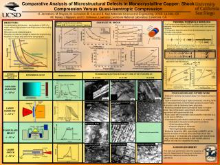
TWINNING THRESHOLD MODELING QUASI-ICE VS. SHOCK • OBJECTIVES: • Understanding deformation mechanisms of [001] Cu under various high-pressure and high-strain rate loading conditions. • Microstructural characterization. • Develop constitutive models to determine slip-twinning transition in Quasi-ICE and shock compression. Shock: Instantaneous loading. Quasi-ICE: Controlled “ramped” loading. • The Prenston-Tonks-Wallace (PTW) constitutive description is used to determine critical twinning pressure in both shock and quasi-isentropic conditions. • PTW equation takes into account both thermal activation regime and dislocation drag regimes. • The instantaneous flow stress is given by: Slices cut from cylindrical samples Where and are work hardening saturation stress and yield stress, respectively. is the value of taken at zero temperature, , θ are the strain and work hardening rate, respectively, and p is a dimensionless material parameter. Dislocation cell size vs. distance from sample free surface: Gas-gun ICE Cell size vs. pressure: quasi-ICE, laser shock and flyer-plate Strong Shock Regime Thermal Activation Regime Strain-rate regimes in shock and Quasi ICE-Gas-Gun • Flow stress is normalized to shear modulus and twinning threshold • assumed to vary with pressure: Dislocation sell size vs. distance from sample free surface: Laser shock Temperature rise in shock and ICE (gas-gun) Hardness, Temp. vs. Peak Pressure: Gas-gun quasi-ice Source: M.Pullington et al., Discovery. DYNAMIC COMPRESSION METHOD TRANSMISSION ELECTRON MICROSCOPY (TEM) OF KEY FEARURES AT: EXPERIMENTAL SETUP PRESSURE PROFILES 50-60 GPA 30-40 GPA 15-30 GPA Twinning at 52GPa Dislocated laths at 34GPa Stacking faults at 26GPa GAS-GUN QUASI-ICE Flow stress vs. peak pressure: gas-gun modeling Flow stress vs. peak pressure: laser modeling ~104 s-1 CONCLUSIONS AND FUTURE WORK • Dislocation activity decreased away from impact surface in • all cases. • TEM revealed twinning at higher pressures, stacking faults • and dislocated laths at intermediate pressures and mostly • dislocation cells at relatively lower pressures. • Modeling revealed twinning threshold lower for higher-strain rate compression experiments and reasonable agreement with experimental data. • Future work will incorporate nanocrystalline materials (e.g. • nc Ni and nc Ni%Fe). • Understanding deformation mechanisms in nc materials: • Dislocation interactions with grain boundaries. • Grain boundary sliding. • Pressure effects on hardness. • Twinning thresholds modeling. • Molecular dynamics (MD), specifically LAMMPS, will be used to simulate and study shock and high-strain-rate phenomena in nc materials and compare with experiments. • High strain rate phenomena in bulk metallic glasses (BMGs) will also be integrated into study. Dislocation cells at 18GPa Dislocation cells and stacking faults at 24GPa Twins/laths at 59GPa LASER QUASI-ICE ~107 s-1 Stacking faults at 30GPa Micro-twins at 57GPa FLYER PLATE IMPACT (Experimental data unavailable) ~104 s-1 Staking faults at 40GPa Dislocation cells at 20GPa Micro-twins at 55GPa ACKNOWLEDGEMENT: LASER SHOCK This work was performed under the auspices of the U.S. Department of Energy by University of California, Lawrence Livermore National Laboratory. ~109 s-1