Radiometer Systems
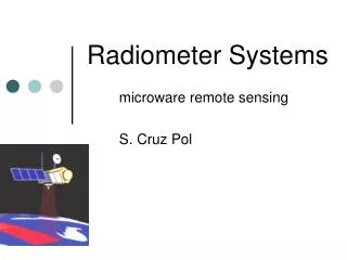
Radiometer Systems. INEL 6669 microware remote sensing S. X-Pol. Tx. Rx. Rx. Microwave Sensors. Radar (active sensor). Radiometer (passive sensor). Radiometers. Radiometers are very sensitive receivers that measure thermal electromagnetic emission (noise) from material media.

Radiometer Systems
E N D
Presentation Transcript
Radiometer Systems INEL 6669 microware remote sensing S. X-Pol UPR, Mayagüez Campus
Tx Rx Rx Microwave Sensors Radar (active sensor) Radiometer (passive sensor)
Radiometers • Radiometers are very sensitive receivers that measure thermal electromagnetic emission (noise) from material media. • The design of the radiometer allows measurement of signals smaller than the noise introduced by the radiometer (system’s noise). UPR, Mayagüez Campus
Topics of Discussion • Equivalent Noise Temperature • Noise Figure & Noise Temperature • Cascaded System • Noise for Attenuator • Super-heterodyne Receiver • System Noise Power at Antenna • Radiometer Operation • Measurement Accuracy and Precision • Effects of Rx Gain Variations UPR, Mayagüez Campus
Topics of Discussion… • Dicke Radiometer • Balancing Techniques • Reference -Channel Control • Antenna-Channel Noise-Injection • Pulse Noise-Injection • Gain-Modulation • Automatic-Gain Control (AGC) • Noise-Adding radiometer • Practical Considerations &Calibration Techniques
TA’ TA Radiometer TB Vout Radiometer’s Task: Measure antenna temperature, TA’ which is proportional to TB, with sufficient radiometric resolution and accuracy • TA’ varies with time. • An estimate of TA’ is found from • Vout and • the radiometer resolution DT.
Noise voltage • The noise voltage is • the average=0 and the rms is
Noisy resistor connected to a matched loadis equivalent to… [ZL=(R+jX)*=R-jX] Independent of f and R!,
Ideal Bandpass Filter B, G=1 ZL Receiver antenna Equivalent Output Noise Temperaturefor any noise source TEis defined for any noise source when connected to a matched load. The total noise at the outputis
input signal input thermal noise Noise Figure, F • Measures degradation of noise through the device • is defined for To=290K (62.3oF!, this = winter in Puerto Rico.) Total output signal Total output noise Noise introduced by device
Noise Figure, F • Noise figure is usually expressed in dB • Solving for output noise power
Equivalent input noise TE • Noise due to device is referred to the input of the device by definition: • So the effective input noise temp of the device is • Where, to avoid confusion, the definition of noise has been standardized by choosing To=290K (room temperature) 75K Examples: 1dB NF is and 3dB NF is What is TE for F=2dB? 288K 170K
Cascade System UPR, Mayagüez Campus
Antenna, TL and Rx Receiver TE2 Transmission Line, TE1
SuperheterodyneReceivers • Rx in which the RF amplifier is followed by a mixerthat multiplies the RF signal by a sine wave of frequency LO generated by a local oscillator (LO). The product of two sine waves contains the sum and difference frequency components • The difference frequency is called the intermediate frequency (IF). The advantages of superheterodyne receivers include • doing most of the amplification at lower frequencies (since IF<RF), which is usually easier, and • precise control of the RF range covered via tuning only the local oscillator so that back-end devices following the un-tuned IF amplifier, multichannel filter banks or digital spectrometers for example, can operate over fixed frequency ranges.
Superheterodyne receiver G=23dB F=7.5dB RF amp Grf ,Frf ,Trf IF amp Gif ,Fif ,Tif Mixer GM,FM,TM Pni Pno G=30dB F=2.3dB G=30dB F=3.2dB LO Example: Trf=290(10.32-1)=638K Tm=1,340K Tif=203K TREC=?
Receiver Transmission Line Equivalent System noise power at antenna terminals • Taking into consideration the losses at the antenna and T.L. with a physical temperature of Tp:
Receiver Transmission Line Equivalent System noise power at antenna terminals • Then the total noise for the system is: For radiometer , Psys = Prec For Radar, S/N= Pr/Psys
Summary • Antenna • Antenna + losses • Receiver • Receiver + T.L. • All of the above
Measurement Accuracy and Precision • Accuracy (“certeza”) – how well are the values of calibration noise temperature known in the calibration curve of output corresponding to TA‘ . (absolute cal.) • Precision (“precisión”)– smallest change in TA‘ that can be detected by the radiometer output.(sensitivity) DT
Total Power Radiometer Super-heterodyne receiver: uses a mixer, L.O. and IF to down-convert RF signal. Usually BRF>BIF UPR, Mayagüez Campus
Detection- power spectra @: UPR, Mayagüez Campus
IF Noise voltage after IF amplifier The instantaneous IF voltage has a time-varying envelopve(t) and phase angle f(t): with zero average The average IF power is equal to the average of the square of vIF(t)
IF x2 square-law detector Noise voltage after detector, Vd The detector voltage is proportional to the square of the envelop voltage: Ve Vd
Low-pass t, gI x2 integrator Noise voltage after Integrator Ve Vd Vout • For averaging the radiometer uses an Integrator (low pass filter). It averages the signal over an interval of time t with voltage gain gI. • Integration of a signal with bandwidth B during that time, reduces the variance by a factor N=Bt,where B is the IF bandwidth.
Low-pass t, gLF x2 integrator Radiometric Resolution, DT Ve Vd Vout • The output voltage of the integrator is related to the average input power, Psys GS is the overall system gain factor. Which can be solved forTA:
Noise averaging • By averaging a large number N of independent noise samples, an ideal radiometer can determine the average noise power and detect a faint source that increases the antenna temperature by a tiny fraction of the total noise power. http://www.cv.nrao.edu/course/astr534/Radiometers.html http://www.millitech.com/pdfs/Radiometer.pdf
The IF voltage • Is a sum of noise signals with same frequency • In phase-domain • Since summing Ns random noise sources, Ve has probability density function pdf given by (see section 5.7 Ulaby & Long 2013) • With an associated standard-deviation to mean ratio: Before integration
The detection voltage Vd has a DC component and an AC component. • The DC component is proportional to the Tsys • The AC component are related to the fluctuations related to the statistical uncertainties of measurement. Before integration the uncertainty is so large that it’s equal to the signal we want to detect. So we need to filter the AC AC component which is equivalent to integrating (averaging) over time.
Integration • Averaging over a B bandwidth and during t time, reduces the variance by a factor N=Bt • Total rms uncertainty Still have fluctuations after LPF but are smaller
Radiometric Sensitivity Since and then • The Noise-caused uncertainty • It’s the minimum (statistically) detectable change in radiometric antenna temperature of the observed scene. Radiometric Sensitivity (or resolution)
Total-power radiometer This doesn’t take into account variations in Gain • It’s also known as Where the bandwidth is called the predetection bandwidth and given a nonuniform transfer funcition is given by Ideal total-power radiometer
Example Radiometer at f=30GHz With T’Rec=600K Observing TA=300K Using B=100MHz and t =0.01sec With gain variations of Find the radiometric resolution, DT Receiver Gain variations DT is due to various causes… • Noise-caused uncertainty • Gain-fluctuations uncertainty • Total rms uncertainty Total-power radiometer resolution including gain variations Also, Try with 10-5 gain variation and no RF amp (TREC’=3000K)
Gain Variations and the Dicke radiometer • As you can see gain variations in practical radiometers, fluctuations in atmospheric emission, and confusion by unresolved radio sources may significantly degrade the actual sensitivity compared with the sensitivity predicted by the ideal radiometer equation. • One way to minimize the effects of fluctuations in both receiver gain and atmospheric emission is to make a differential measurement by comparing signals from two adjacent feeds. The method of switching rapidly between beams or loads is called Dicke switching after Robert Dicke, its inventor. [Using a double throw switch.]
Dicke radiometer Unity-gain amplifiers (-) & (+) The radiometer voltage is: The switching rate isfs switching periodts is much shorter than integration time.:
Dicke Radiometer Noise-Free Pre-detection Section Gain = G Bandwidth = B Switching rate, fs= 1/ts • Dicke Switch • Synchronous Demodulator Nyquist sampling theorem
Dicke radiometer The radiometer switches rapidly between reference and antenna using the Dicke switching
Dicke Radiometer resolution The output voltage of the low pass filter in a Dicke radiometer looks at reference and antenna at equal periods of time with the minus sign for half the period it looks at the reference load (synchronous detector), so The receiver noise temperature cancels out and the total uncertainty in T due to gain variations is
Dicke radiometer resolution • The uncertainty in T due to noise when looking at the antenna or reference (half the integration time) • Unbalanced Dicke radiometer resolution Example: B=100MHz, t=1s, T’rec= 700K, DG/G=.01, Tref=300K for T’A=0K and 300K, for Total P radiometer and Dicke radiometer
Balanced Dicke A balanced Dicke radiometer is designed so that TA’= Tref at all times. In this case,
Balancing Techniques • Reference Channel Control • Antenna Noise Injection • Pulse Noise Injection • Gain Modulation • Automatic Gain Control
Vc Reference Channel Control Tc Force T’A= T ref Switch driver and Square-wave generator, fS Vout =? Pre-detection G, B, TREC’ Vout TA’ Integrator t Synchronous Demodulator Tref *Measures vc Feedback and Control circuit Vc Variable Attenuator at ambient temperature To L TN Noise Source
Reference Channel Control TN and To have to cover the range of values that are expected to be measured, TA’ • If 50k<TA’< 300K • Use To= 300K and need cryogenic cooling to achieve TN =50K. • But L cannot be really unity, so need TN < 50K. To have this cold reference load, one can use • cryogenic cooled loads (liquid nitrogen submerged passive matched load) • active “cold” sources (COLDFET); backward terminated LNA can provide active cold source.
Cryogenic-cooled Noise Source • When a passive (doesn’t require power to work) noise source such as a matched load, is kept at a physical temperature Tp , it delivers an average noise power equal to kTpB • Liquid N2 boiling point = 77.36°K • Used on ground based radiometers, but not convenient for satellites and airborne systems.
Active “cold or hot” sources • http://www.maurymw.com/ • http://sbir.gsfc.nasa.gov/SBIR/successes/ss/5-049text.html
Active noise source: FET • The power delivered by a noise source is characterized using the ENR=excess noise ratio where TNis the noise temperature of the source and To is its physical temperature. Example for 9,460K: ENR= 15 dB
Switch driver and Square-wave generator, fS TA” TA’ Vout Pre-detection G, B, Trec’ Coupler Integrator t Synchronous Demodulator Tref L Feedback and Control circuit Vc TN Noise Source Antenna Noise Injection *Measures vc Force T”A= T ref = T o T’N Variable Attenuator Fc = Coupling factor of the directional coupler
Antenna Noise Injection • Combining the equations and solving for L from this equation, we see that Toshould be>TA’ • If the control voltage is scaled so that Vc=1/L, then Vcwill be proportional to the measured temperature,