Download
1 / 51
510 likes | 721 Vues
Part III: Overview of Technologies, ATM, and IP. Overview of Networking Technologies Developments High-speed Characteristics Switching Techniques ATM (Asynchronous Transfer Mode) Principles of Cell Switching ATM Connection Management ATM Layer and Adaptation Layer IP (Internet Protocol)

E N D
Part III: Overview of Technologies, ATM, and IP • Overview of Networking Technologies • Developments • High-speed Characteristics • Switching Techniques • ATM (Asynchronous Transfer Mode) • Principles of Cell Switching • ATM Connection Management • ATM Layer and Adaptation Layer • IP (Internet Protocol) • Key Elements • Protocol Stack
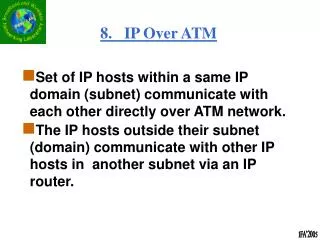
Networks • Networks provide an infrastructure for: • Interconnecting machines or services (connectivity), • Making available scarce resources (resource sharing), • Equalizing traffic volumes (load balancing), and • Providing alternative fallbacks (reliability). • Structuring networks according to dimensions: • Expansion (LAN, MAN, WAN), • Topology (star, ring, bus, meshed), • Performance (low-speed, high-speed, real-time), • Administration (public, private), and • Task (internet or physical net, intranet or virtual net).
Inventions in Telecommunications 1012 1011 1010 109 108 107 106 105 104 103 102 10 1 Monomode optical fiber 16 Gbit/s Multimode optical fiber 140 Mbit/s Monomode optical fiber 565 Mbit/s Multimode optical fiber 45 Mbit/s 108000 voice channels over cable 32000 voice channels over cable 3600 voice channels over cable and microwave 1800 voice channels over cable and microwave 600 voice channels over cable (T3) and microwave 1850 1860 1870 1880 1890 1900 1910 1920 1930 1940 1950 1960 1970 1980 1990 2000 60 voice channels over coaxial cable Carrier telephony carries 12 voice channels on wire First carrier telephony First telephone channels constructed Baudot multiplex telegraph (6 machines on one line) Printing telegraph systems Early telegraphy (Morse code dots and dashes) Oscillating needle telegraph experiments Bandwidth bit/s Year
2 10 1 10 0 10 0 1 2 3 10 10 10 10 Transmission Media • Fiber optical media: • Low error rates, long distances, low attenuation. Copper (Coaxial) Copper (UTP) Attenuation [dB/km] Fiber (Gradient) Fiber (Multimode) Fiber (Monomode) Frequency [MHz]
Bandwidth [kbit/s] LAN POTS WAN Local Area Network Plain Old Telephone Service Wide Area Network 7 10 6 10 LAN 5 10 WAN 4 10 3 10 POTS 2 10 1 10 Time [year] 0 10 1975 1980 1985 1990 1995 2000 2005 Evolution of Bandwidth • Last MileProblem: • Connectionbetween thehome and thebackboneis serious. • Requires ahuge capitalinvestment. • Fiber ignoresthe lastmile problem.
High Speed Networks – Overview (1) • High Speed Local Area Networks (LAN): • Fast Ethernet: 100 Mbit/s • Gigabit Ethernet: 1.0 Gbit/s • HIPPI: 800 Mbit/s • Fiber Channel: 100, 200, 400, or 800 Mbit/s • High Speed Token Ring: 100 Mbit/s (1 Gbit/s) • High Speed Metropolitan Area Networks (MAN): • FDDI: 100 Mbit/s • FDDI-II: 100 Mbit/s (incl. isochronous channels) • DQDB: 34 Mbit/s, 155 Mbit/s, or 622 Mbit/s • High Speed Wide Area Networks (WAN): • ATM-based B-ISDN: e.g., 2, 34, 155, 622, or 2,400 Mbit/s
High Speed Networks – Overview (2) • Carrier support (physical layer): • Plesiochronous Digital Hierarchy (PDH): • e.g., DS-0: 0.064 Mbit/s (= 1 voice channel) • T-1 (USA): 1.544 Mbit/s ( 24 voice channels) (also called DS-1) • E-1 (Europe): 2.048 Mbit/s • E-3 (Europe): 34.368 Mbit/s • T-3 (USA): 44.736 Mbit/s (also called DS-3) • Synchronous Digital Hierarchy (SDH) orSynchronous Optical Network (SONET): • e.g., STS/OC-1: 51.84 MBit/s • STS/OC-3: 155.52 MBit/s ( STM-1) DS: Digital Signal T: Telephone Line OC: Optical Carrier STS: Synchronous Transfer Signal Level
High Speed Networks – Overview (3) • Carrier support (physical layer) continued: • Wavelength Division Multiplexing (WDM) • Access technologies: • Cable TV • Frame Relay (FR) • xDSL (Digital Subscriber Line) • Satellite networks and wireless local loop • Service technologies: • Switched Multimegabit Data Service (SMDS)
Transmission rate [Mbit/s] 3 10 2 10 1 10 0 10 -1 10 -2 10 -3 10 Distance [km] -3 -2 -1 0 1 2 3 4 10 10 10 10 10 10 10 10 Network Dimensions FDDI, DQDB, CRMA HSTR Fast Ethernet xDSL 2000 Metropolitan Area Network 1995 HIPPI 1990 ATM-based B-ISDN System Bus 1980/90 Local Area Network 1995 Wide Area Network 2000 STM ATM LAN 1985 Token Ring Ethernet 1990 1980 N-ISDN X.25
Protocol Layer Architecture – Examples Voice telnet ... Voice IP ... IP ... ATM PPP Video Voice TransmissionConvergence HDLC WDM SDH/SONET ADSL SDH/SONET ADSL: Asymmetric Digital Subscriber Loop ATM: Asynchronous Transfer Mode HDLC: High Data Link Control IP: Internet Protocol PPP: Point-to-Point Protocol WDM: Wavelength Division Multiplexing
Characteristics of High Speed Networks • Characteristics of high speed networks: • Low bit error rate (fiber optical media), • Higher packet error rate (buffer overflow), • Existing Jitter (different buffer lengths), • Small transmission units (cells), • Many connections (context data), • High bandwidth (fiber optical media), and • Extreme bandwidth-delay product. • Protocols have to deal with these issues to alleviate influences of delayed, corrupted, or lost data.
File Transfer Example File size: 1 Mbyte Link: San Diego – Boston Signal delay: 25 ms • 64 kbit/s channel: • 64 kbit/s * 25 ms = 1,600 bit • 0.02 % of file on link • 2 Mbit/s channel: • 2 Mbit/s * 25 ms = 50,000 bit • 0.6 % of file on link • 1 Gbit/s channel: • 1 Gbit/s * 25 ms = 25,000,000 bit • 8 ms for transmission, 17 ms idle BOS SAN 5000 km SAN BOS 1,600 bit 50,000 bit 25,000,000 bit Bits are smaller – not faster !
Effects on Data in Transit • Signal delay is dominating the transmission delay. • This grows worse for high transmission rates. • Buffer overflows dominate occurring errors. • The effect grows worse for fast and real-time traffic. • Error recovery has to be a trade-off between a waste of bandwidth or extending delays. • Bandwidth is much cheaper than tolerating high delays. • Multimedia applications normally don´t like delays. • A huge amount of data is in transit within high speed and long distance networks Path Capacity PC: PC = B * Dsignal B: Bandwidth, Dsignal: Signal delay.
Switching Techniques – Overview • Switching Techniques: • Based on circuits, cells, frames, or packets. • Circuit switching suffers from fixed bandwidth constraints for bursty traffic. • Packet switching allows for variable bandwidth. Intricacy Simple Complex Behavior of Bandwidth Fixed Variable Circuit Switching (STM) Multirate Circuit Switching Fast Circuit Switching Fast Packet Switching Frame Relay Frame Switching Packet Switching ATM
Circuit Switching • Circuit information are stored during establishment times in a translation table. • Delay is determined by thepropagation delay and theprocessing in switches. • Bounded to 450s by ITU-T. • Bit error rates are causedby single bit errors (switch-ing malfunction) or bursts(loss of synchronization). • Inflexible, e.g., G.703 PCM. • Fixed bandwidth. Incoming Link Time Slot Outgoing Link Time Slot 3 2 … 1 O1 O2 O3 … O1 O2 O3 … O1 O2 O3 … l1 l2 lm 1 2 … m 4 2 … m 1 2 … m 1 m … 1 1 2 … m
Packet Switching • Based on user data that are encapsulated in packets. • Concept is based on technology available in the 60s: • Erroneous links: • Link-based error control in complex protocols. • Low bandwidth links: • High delays (due to retransmissions) and low speed (due to protocol processing) • Lacking support of real-time and multimedia traffic • Software-based protocol implementations: • Variable sized packets require a complex buffering. • X.25 is the oldest example of packet switching nets.
Frame Relay (1) • Frame Relay supports connection-oriented services. • Subscriber Network Interface (SNI) defined between customer (router) and PTO equipment. • Support of pure data, not particularly voice etc. • Multiplexes flows of data being divided in data blocks. • Flows are carried in virtual channels which may exceed their bandwidth as other channels are idle. • Frame Relay may carry X.25 packets/frames. • Performance: • Different implementation approaches exist, however, 2 Mbit/s access speeds are common. • Insufficient guarantees on bandwidth and delay variation. PTO: Public Telecommunication Operator
Byte 1 2 variable 2 1 Flag Address Payload FCS Flag 01111110 01111110 DLCI C/R EA DLCI FECN BECN DE EA bit 6 1 1 4 1 1 1 1 Frame Relay (2) • Physical and data link layer specifications available. • The data link layer is based on LAPD (ISDN): • Data link services: addressing (DLCI, local significance). • Error control is left out as an end-to-end function. • Core LAPD frame: DLCI: Data Link Connection Identifier C/R: not used EA: Extended Address FECN: Forward Error Congestion Notification BECN: Backward Error Congestion Notification DE: Discard Eligibility
Frame Relay (3) • Frame Relay DLCI assignments: • A simple sample Frame Relay network: 0 Reserved for Call Control Signaling 1-15 Reserved 16-1007 Assigned to Permanent Virtual Circuits (PVC) 1008-1022 Reserved 1023 Local Management Interface User A 1007 Frame Relay Interface Frame Relay Interface 16 Permanent Virtual Circuits Frame Relay Interface User B 1007 User C 145 16, 145, 1007: DLCI
Comparison • Summary of important functional differences: Frame Switching or – Frame Relay – – – – X.25 – Connection-oriented Connectionless Frame Boundaries Bit Stuffing CRC Error-Control ARQ Flow-Control Multiplexing of log. Channels Heavy weight Light weight Technology CRC: Cyclic Redundancy Check
Part II: Overview of Technologies, ATM, and IP • Overview of Networking Technologies • Developments • High-speed Characteristics • Switching Techniques • ATM (Asynchronous Transfer Mode) • Principles of Cell Switching • ATM Connection Management • ATM Layer and Adaptation Layer • IP (Internet Protocol) • Key Elements • Protocol Stack
Cell-based Switching • Integration of a variety of services: • Bursts are smoothened. • Isochronous data are delivered according to their jitter. • Data may be multiplexed statistically, if the overall bandwidth is sufficient. • Efficiency: statistical multiplexing gain. • Delay problems occur in case of sending packets of different length. Extremely long blocking can be avoided, if cells of fixed-size are used. If the overall cell length is too big, a similar problem appears.
User Data User Data User Data SAR User Data SAR Handling Cells – Segmentation/Reassembly • To sent packets over cell-based networks, packets have to be segmented and reassembled again. • The segmentation and reassembly (SAR) functionality is placed right above the cell level. Packet Cells Packet Cell Header HLP . . . SAR Header SAR HLP UD HLP Higher Layer Protocol Header . . . UD Cell SAR HLP Cell User Data Cell SAR User Data SAR Total Cell Length Cell Payload Length
Core ATM-Switch Customer Premises Equipment Edge ATM-Switch ATM- Switch ATM- Switch ATM- Switch ATM- Switch ATM- Switch ATM- Switch Structure of an ATM-based B-ISDN Network ATM-connected MM-Workstation UNI NNI NNI UNI NNI NNI NNI UNI ATM-connected MM-Workstation ATM: Asynchronous Transfer Mode MM: Multimedia NNI: Network Node Interface UNI: User Network Interface
Management Plane Control P. User P. Higher Layer Protocols Plane Management Layer Management ATM Adaptation Layer ATM Layer Physical Layer B-ISDN Reference Model – I.321 • Modeling communication systems is done in a logically hierarchical structure, e.g., ISO/OSI BRM. • Relation between OSI and B-ISDN/ATM undefined. • The plane approach has been used within B-ISDN. P.: Plane
VCC 1 VPC 1 VPC 2 VPC 3 VCI 1 VCI 3 VCI 2 VPI 1 VPI 2 VPI 3 VPI 4 VPI 5 ATM End-system ATM Cross-connect ATM Switch ATM Switch ATM Cross-connect ATM End-system VPL 1 VPL 2 VPL 3 VPL 4 VPL 5 ATM Connections (1) • Connections, links, ATM equipment, and identifiers: “Connections” Identifiers Equipment Links VC: Virtual Channel, VP: Virtual Path, L: Link, I: Identifier, C: Connection
ATM Connections (2) • Hierarchical connection concept includes: • Virtual Connections are identified by two identifiers, which are significant only locally per link in the virtual connection. • Error-control is done end-to-end only, if required. • High quality links and a good call acceptance control. • Flow-control is not provided. • High bandwidth delay product. • Virtual Channel (VC) is a uni-directional channel, identified by the Virtual Channel Identifier (VCI). • Dynamically allocatable connections. • Virtual Path (VP) contains a group of VCs, identified by the Virtual Path Identifier (VPI). • Statically allocatable connections.
VCI1 VCI2 VPI1 VPIk Link VCIn VCIm ATM Connections (3) • Simultaneous support of many thousands of VCs requires the ATM cell to carry the VCI field. • Supporting many semi-permanent connections between endpoints, carrying many grouped VPs requires the ATM cell to carry the VPI field. Pre-assigned VPI/VCI values: 0/0 Unassigned, idle 0/1 Meta-signaling 0/3 Segment flow (between VP end-points, F4) 0/4 End-to-end F4 flow 0/5 Signaling 0/15 SMDS 0/16 ILMI VPIVirtual Path Identifier VCI Virtual Channel Identifier ILMI: Integrated Layer Management Interface SMDS: Switched Multimegabit Data Service
ATM Switching (1) • Two types of switching may be performed. • VP switching (ATM Cross-connect): • Switching between VPs, • No evaluation and change of VCIs, • Change of VPIs, and • Variable number of VCs per VP possible. • VC/VP switching (ATM Switch): • Switching in close cooperation between VCs and VPs, • Evaluation of VCI and VPI in an intermediate system, • Change of VCI and VPI if necessary, and • Incoming VCs of one VP may be distributed between many outgoing VPs.
ATM PHY ATM PHY ATM PHY ATM Switching (2) • Use of VPI in a B-ISDN network (cross-connect). VPIin VPIout 5 7 VPI = 7 VCI = 1, 2, 3 VPI = 5 VCI = 1, 2, 3 B VPIin VPIout 7 5 9 7 1 VPI = 7 VCI = 1, 2, 3 VPIin VPIout 7 3 2 B-ISDN Network A C VPI = 9 VCI = 3, 4 VPI = 3 VCI = 3, 4 3 VPI = 7 VCI = 3, 4
ATM PHY ATM PHY ATM PHY ATM Switching (3) • Use of VPI-VCI in a B-ISDN network (ATM switch). VPI-VCIin VPI-VCIout 5.1 7.2 5.2 7.1 5.3 7.3 VPI = 7 VCI = 1, 2, 3 VPI-VCIin VPI-VCIout 7.1 5.1 7.2 7.3 7.3 5.2 9.3 7.4 9.4 5.3 VPI = 5 VCI = 1, 2, 3 B 1 VPI-VCIin VPI-VCIout 7.3 3.4 7.4 3.3 VPI = 7 VCI = 1, 2, 3 2 B-ISDN Network A C VPI = 9 VCI = 3, 4 VPI = 3 VCI = 3, 4 3 VPI = 7 VCI = 3, 4
ATM Layer – UNI Cell Format • GFC: Generic Flow-Controlused at the service interface. • PT: Payload Type definescontents of a cell: • User data congested, • User data non-congested, • Operation And Maintenance(OAM) cells, and • Resource management cells. • CLP: Cell Loss Priority to identify low/high priority cells. • HEC: Header Error Control. 5 Byte 48 Byte Header Payload Byte VPI VCI PT CLP VCI HEC 1 2 3 4 5 GFC VPI VCI 1 2 3 4 5 6 7 8 bit UNI: User-Network Interface
ATM Layer – NNI Cell Format • VPI: Virtual Path Identifiercomprises of 12 bit length. • PT: Payload Type definescontents of a cell: • User data congested, • User data non-congested, • Operation And Maintenance(OAM) cells, and • Resource management cells. • CLP: Cell Loss Priority to identify low/high priority cells. • HEC: Header Error Control. 5 Byte 48 Byte Header Payload Byte VCI PT CLP VPI VCI HEC 1 2 3 4 5 VPI VCI 1 2 3 4 5 6 7 8 bit NNI: Network-Network Interface
Structure of the AAL • AAL includes sublayers: • Segmentation andReassembly (SAR) between packets/cells. • Convergence sublayer(CS) for service-dependent adaptation: • Common Part Con-vergence Sublayer(CPCS) and • Service Specific Con-vergence Sublayer(SSCS). • Layers may be empty. Class A Class B Class C/D Class C/D CS-1 SAR-1 AAL 1 SSCS-2 CPCS-2 SAR-2 AAL 2 SSCS-3/4 CPCS-3/4 SAR-3/4 AAL 3/4 SSCS-5 CPCS-5 SAR-5 AAL 5 ATM Adaptation Layer ATM Layer
AAL Comparison Criteria AAL 1 AAL 3/4 AAL 5 AAL 2 AAL Service Class Message Delimiter Advanced Buffer Allocation Multiplexing CS Padding CS Protocol Overhead CS Checksum SAR Payload SAR Protocol Overhead SAR Checksum A no no no 0 0 no 46/47 Byte 1/2 Byte no B no no yes 0/46 Byte 2 Byte no 1/47 Byte 3 Byte no C/D BTAG yes yes 4 Byte 8 Byte no 44 Byte 4 Byte 10 bit C/D Bit in PTI no no 0/47 Byte 8 Byte 32 bit 48 Byte 0 no PTI: Payload Type Information
ATM Functions per Layer – Summary Layer AAL ATM PHY Subl. CS SAR TC PM Function Handles transmission errors Handles lost and misinserted cell conditions Handles timing between source and destination Handles cell delay variation Segments higher-layer information into 48 Byte fields Reassembles cell payload in higher layer information Multiplexes cells from different ATM channels Generates cell header (first four bytes) Performs payload type discrimination Performs traffic shaping and flow control Routes and switches cells as needed Indicates cell loss priority and selects cells for discarding HEC header sequence generation and verification Cell delineation Transmission frame generation and recovery Bit timing
Part II: Overview of Technologies, ATM, and IP • Overview of Networking Technologies • Developments • High-speed Characteristics • Switching Techniques • ATM (Asynchronous Transfer Mode) • Principles of Cell Switching • ATM Connection Management • ATM Layer and Adaptation Layer • IP (Internet Protocol) • Key Elements • Protocol Stack
IP Technology • Key elements of the technology used in the Internet: • Packet switching, using datagrams • No connection-dependent state information in the network • Distributed management • Many physical subnetwork technologies • One network protocol • Two transport protocols • Infrastructure for hundreds of different distributed applications • Scalability: to accommodate exponential growth
IP Protocol Stack Application layer HTTP FTP DNS Transport layer TCP UDP Internet layer IP Routing Phys. Network layer Ethernet ATM DECnet
Internet Protocol (IP) • IPv4 shows addressing problems: • Nearly exhausted Class B addresses. Classless Inter-domain Routing (CIDR) provides short-term solution only. • Routing tables grow extremely fast . • IP unicast address space will run out due to radipdly, e.g., increasing Internet hosts and low-end Internet devices. • Next Generation Internet, IPv6, delivers solutions: • Extended addressing: 128 bit addresses. • Address hierarchy levels (hierarchy: subscriber, subnet, ...) • Anycast addresses to reach the “nearest” node of a group (in terms of the routing metric). • Simplified IP header, including a flow label.
International ISP “Backbone” Large Enterprise RegionalISP B Small Enterprise SOHO Internet Network Model ISP: Internet Service Provider SOHO: Small Office and Home
Example – Backbone ISP: UUNET http://www.caida.org/Tools/Mapnet/Backbones/
Example – Regional ISP: Switch http://www.switch.ch
Switch – UUNET Interconnection http://www.switch.ch
Router Router Router Router Multicast Router Router Router Router Router Route Server DNS Server Router Web Server Router Router Router Co-location Model • Extensions broadens the model by other services: • More than a pure routing and traffic exchange role. • Content provider supported, e.g., with high volumes, selection of non-local transit providers. • E.g., Multicast, Web, DNS, policy-based route services.
Services Integrated Internet Best-effort IntServ DiffServ QoS Guarantees Configuration Zone State Information Required Protocols Status no none entire network none none operational per data stream per session (dynamic) end-to-end data stream per data stream, in router signaling (RSVP) matured aggregated log-term (static) domain- oriented (none, in BB, in edge router) bit fields (BB, COPS) worked on IntServ: Integrated Services, DiffServ: Differentiated Services, QoS: Quality-of-Service RSVP: Resource Reservation Protocol, BB: Bandwidth Broker, COPS: Common Open Policy Service
Control Data Application Admission Control Resource Reservation Policy Control Packet Scheduler Packet Classifier IntServ Implementation • Integrated Services Architecture (IntServ) supports best-effort and guaranteed services. • Traffic control functions: • Admission control, • Packet classifier, and • Packet scheduler. • Optional: Policy control (COPS). • Protocol support: • Resource reservation,E.g., RSVP (Resource Reservation Protocol). • Host and router require similar functionality.
The DiffServ Approach • Requirements for Differentiated Services proposals: • Aggregated bandwidth allocation without the need of per-session signaling and complex router state, • Aggregated QoS guarantees with edge-complexity, • Long-term service contracts within a single domain, • Integrated and simplified accounting, • Better traffic isolation for performance predictability, and • Better services for users willing to pay more. • A set of new proposals for DiffServ: • Expedited Forwarding (EF) and • Assured Forwarding (AF).
References (1) • F. Fluckiger: Understanding Networked Multimedia; Prentice Hall, London, England, 1995, ISBN 0–13–190992–4. • R. Steinmetz: Multimedia Technologie; Springer Verlag, Bonn, Germany, 1999, ISBN 3-540-62060-5. • M. de Prycker: Asynchronous Transfer Mode – Solution for Broadband ISDN; 3rd Edition, Prentice Hall, Englewood Cliffs, New Jersey, U.S.A., 1995, ISBN 0–13–342171–6. • ITU-T – Maintenance Principles: Frame Relay Operation and Maintenance Principles and Functions; I.620, October 1996.