Download
1 / 12
130 likes | 259 Vues
BJT and MOS Class AB Output Stages: Comparison and Contrast. Mohsen Mesbah. Motivation.

E N D
BJT and MOS Class AB Output Stages:Comparison and Contrast Mohsen Mesbah
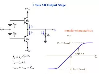
Motivation • So far we examined various classes of output stages based on bjt transistors. However, another useful output stage configuration is based on MOS transistors. The aim of this presentation is to develop a good understanding of this class. • At first, we take a brief review on MOS operation in the following diagram.
Brief Review on MOS operation Overdrive Voltage Increases
Let’s Start Step-by-Step Analysis! Diode Connected Transistors!
Step-by-Step Analysis contd. In case of constant bias current from M3, the LHS is constant, so increasing Vgs1 decreases Vsg2 and vice versa. Hence, output bias current is under controlled by diode connected transistors!
Derivation of maximum output swing • Despite being similar to the bjt counterpart relation, it bears some difficulties: • The gate-source voltage includes a threshold component that is absent in the base-emitter voltage. • It suffers from the body effect since Vt changes by further changes in Vo. • Overdrive voltage rises rapidly with increasing current than bjt counterpart. Because overdrive voltage is proportional to the square root of the current but the base-emitter voltage is proportional to the logarithm of the current.
So, with respect to limitations illustrated above, is there any alternatives to enhance the performance of the circuit?
Step-by-Step Analysis contd. So, as depicted in the above relation, the output swing is increased in comparison with single class AB MOS configuration.