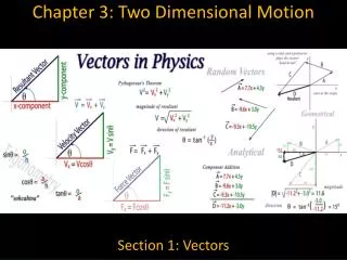
Chapter 7 Motion and Dimensional Measurement Instruments
1.32k likes | 1.59k Vues
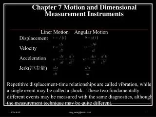
Chapter 7 Motion and Dimensional Measurement Instruments. Liner Motion Angular Motion. Displacement Velocity Acceleration Jerk( 冲击量 ).

Chapter 7 Motion and Dimensional Measurement Instruments
E N D
Presentation Transcript
Chapter 7 Motion and Dimensional Measurement Instruments Liner Motion Angular Motion Displacement Velocity Acceleration Jerk(冲击量) Repetitive displacement-time relationships are called vibration, while a single event may be called a shock. These two fundamentally different events may be measured with the same diagnostics, although the measurement technique may be quite different. cary_wang@sohu.com
Conversion factors for distance 1 inch (in) = 2.540000 centimeter (cm) 1 foot (ft) = 12 inches (in) 1 yard (yd) = 3 feet (ft) 1 mile (mi) = 5280 feet (ft) cary_wang@sohu.com
Conversion factors for velocity 1 mile per hour (mi/h) = 88 feet per minute (ft/m) = 1.46667 feet per second (ft/s) = 1.60934 kilometer per hour (km/h) = 0.44704 meter per second (m/s) = 0.868976 knot (knot – international) cary_wang@sohu.com
Chapter 7 Motion and Dimensional Measurement Instruments A. Motion and Displacement(运动量和位移量) • Resistive Potentiometers • Ideal Characteristics • Resistive potentiometers are used for two basic functions: • i). Voltage Control (Wheatstone Bridge – variable resistor) • ii. Motion Measurement (linear or angular) Range ~ 102 – 105 Ohms/inch cary_wang@sohu.com
Resistive PotentiometersDeviations for Ideality • Finite Resolution • ~ 500 – 1,000 “turns”/inch (20-40 /mm) for typical wire wrapped devices cary_wang@sohu.com
Resistive Potentiometers Deviations from Ideality (cont.) ii. Loading Any “reading” device constitutes a “load” on the system which is being read. More specifically, the device draws current, which causes a drop in voltage of the “source” (eo in this case). In effect, an additional resistance, Rm, is inserted in parallel with the device. For a voltage divider, the result is: Note: “Max %” Error ~ 15 RP/Rm (Text: p. 233) Note: As RP/Rm 0, eo/eex xi/xt (“High” input impedence Low i draw) cary_wang@sohu.com
R2 cary_wang@sohu.com
Resistive Potentiometers Deviations from Ideality (cont.) iii. Power Constraints Since RP is limited (since Rm is typically 106 Ohms), sensitivity is maximized by increasing eex (in order to maximize eo). However, there are power constraints due to “Joule Heating” (i2R = iV) PMAX ~ 5 Watts (typically) which gives Example P = 2 Watts RP = 104 Ohms eex, max ~ 150 V (total) cary_wang@sohu.com
Some Pictures of Potentionmetric Displacement Sensors Rotational Motion Linear Motion cary_wang@sohu.com
B. Resistance Strain Gauge(电阻应变规) Consider a conductor having a uniform cross-sectional area, Ac, and a length, L, made of a material having a resistivity, . For this electrical conductor,the resistance,R,is given by: cary_wang@sohu.com 8
If the conductor is subjected to a normal stress along the axis of the wire,the cross-sectional area and the length will change,resulting in a change in the total electrical resistance,R. The total change in R is due to several effects,as illustrated in the total differential: Which may be expressed in terms of Poisson’s ratio νp as: cary_wang@sohu.com
The dependence of resistivity on mechanical strain is called piezoresistance. And may be expressed in terms of a piezoresistance coefficient, (纵向压阻效应系数)defined by: With this definition,the change in resistance may be expressed: cary_wang@sohu.com
Gauge Factor The change in resistance of a strain gauge is normally expressed in terms of an empirically determined parameter called the gauge factor,GF. It can be expressed as: The gauge factor is dependent on the Poisson ratio for the gauge material and its piezoresistivity. cary_wang@sohu.com
Semiconductor Strain Gauges Silicon crystals are the basic material for semiconductor strain gauges; the crystals are sliced into very thin sections to form strain gauges. *In general,materials exhibit a change in resistivity with strain,characterized by the piezoresistance coefficient, cary_wang@sohu.com
A simple strain gauge Wheatstone bridge circuit is shown in right FIGURE. Consider the case all the resistors are equal,and the bridge balanced,if the gauge experiences a change in resistance ,then cary_wang@sohu.com
EXAMPLE A strain gauge,having a gauge factor of 2,is mounted on a rectangular steel bar( ),as shown in Figure. The bar is 3cm wide and 1cm high,and is subjected to a tensile force of 30kN. Determine the resistance change of the strain gauge. If the resistance of the gauge was 120 in the absence of the axial load. cary_wang@sohu.com
KNOWN: GF=2 ; FN=30kN ; FIND: The resistance change of the strain gauge for a tensile force of 30kN. SOLUTION: The stress in the bar under this loading condition is: And the resulting strain is cary_wang@sohu.com
For strain along the axial of the strain gauge,the change in resistance is: cary_wang@sohu.com
Linear Variable Differential Transformer(LVDT) • Basic Principles • AC current flows through “primary” coil, due to excitation voltage eex. • Current is “induced” through a pair of secondary coils (eo1, eo2). • The frequency of the induced AC current is the same as the excitation frequency. • The amplitude of the induced current in each secondary coil depends upon the location of the movable “core”. cary_wang@sohu.com
An LVDT transducer shown in FIG comprises a coil former on to which three coils are wound. • The primary coil is excited with an AC current, the secondary coils are wound such that when a ferrite core is in the central linear position, an equal voltage is induced in to each coil. • The secondary are connected in opposite so that in the central position the outputs of the secondary cancels each other out. cary_wang@sohu.com
LVDT Basic Principle (cont). If core is located in “null” position then secondary voltages are equal, as illustrated below. cary_wang@sohu.com
LVDT Basic Principles (cont.) If the two secondary coils are connected in anti-series (+ + and - -) then the resulting output is the difference between the outputs of the individual seconary coils. The amplitude depends upon the position of the rod. (There is also a Phase shift between eex and eo as we will show later) cary_wang@sohu.com
LVDT As Displacement Sensor The input, xi, is the MOTION of the rod to which the core is connected. The output, eo, is the voltage difference between the induced voltages in the two secondary loops. Note: The output is inherently AM modulated (The “carrier” is AC excitation of the primary loop). Note: Phase Shift occurs as xi crosses “null” point cary_wang@sohu.com
LVDT – Simulated Output (lvdtsim01.dsb) xi eo cary_wang@sohu.com
More Accurate LDVD Simulation (lvdtsim02) xi eo,1 eo,2 eo cary_wang@sohu.com
A Closer Look at the LVDT Output (Note Phase Shift at Null Point) cary_wang@sohu.com
How Do We Recover the LVDT Signal? Motion LVDT output Demod LVDT Recovered Motion l(vdtsim03.dsb) cary_wang@sohu.com
LVDT Signal Recover – Frequency Domain Motion LVDT output Demod LVDT Recovered Motion cary_wang@sohu.com
The DasyLab Program cary_wang@sohu.com
LVDTs – Some Math(Where does the Phase shift come from?) cary_wang@sohu.com
Bandwidth of LVDT (Demodulation) The “transfer function” derived previously describes the sensitivity of the output signal to the Excitation frequency of the Primary Loop (NOT the frequency response to input motion!!) The frequency response to input motion is dictated by the requirement to Demodulate the signal. Let’s look at this in more detail. cary_wang@sohu.com
Modulation/Demodulation Amplitude Modulation Process Amplitude Demodulation Process Input Signal s (t) Output Carrier c (t) Carrier c (t) Primary Loop Excitation C LVDT Transducer AM Output C + S C - S Demodulated Output 2 C + S S 2C - S S Signal S cary_wang@sohu.com
Frequency Domain Picture(Fill in in Class) We need to filter demodulated output such that we transmit at s and attenuate at 2c z cary_wang@sohu.com
Some Examples (Worked in Class) Example 1: Single Stage RC filter c = 10 KHz (a typical value) What is Maximum frequency of motion that can be detected with LVDT? (Lets verifty our conclusion with DaisyLab) cary_wang@sohu.com
Piezoelectric Materials - Intro • Piezoelectricity describes the phenomenon of generating an electric charge in a material when subjecting it to a mechanical stress (direct effect) and conversely generating a mechanical strain in response to an applied electric field. • Discovered in 1880 by Pierre and Jacques Curie • Types • Natural and Synthetic Crystals (单晶压电晶体): • Quartz, Rochelle Salt (Natural)(石英、罗歇尔盐(四水酒石酸钾钠)) • Lithium Sulfate, Ammonium Dihydrogen Phosphate (Synthetic) (硫酸锂、磷酸二氢铵) • Piezoceramic elements(多晶压电陶瓷) • Lead Zirconate Titanate (PZT)(锆钛酸铅) • Barium Titanate (极化的铁电陶瓷(钛酸钡)) , Cadmium Sulfide • Piezoelectric Polymer (高分子压电薄膜) • Polyvinylidene Fluoride (PVDF) cary_wang@sohu.com
Piezoelectric Materials • Piezoelectric materials belong to a class of materials called Ferroelectrics. Piezoelectric Crystals exhibit the piezoelectric effect naturally, without any processing. • Piezoelectric Ceramics must be polarized by applying a strong electric field to the material while it is simultaneously heated. They are (isotropic) before poling and after poling exhibit tetragonal symmetry (anisotropic structure) below the Curie temperature. Above this temperature they lose the piezoelectric properties. • On a microscopic level the materials are made of ions which is the reason for electric dipole behavior. Groups of dipoles with parallel orientation are called Weiss domains. The Weiss domains are randomly oriented in the raw ceramic material, before the poling treatment has been finished. For this purpose an electric field (> 2000 V/mm) is applied to the (heated) piezo ceramics. • When an electric voltage is applied to a poled piezoelectric material, the Weiss domains increase their alignment proportional to the voltage. The result is a change of the dimensions (expansion, contraction) of the PZT material. cary_wang@sohu.com
Piezoelectric Materials (PZT) Unpolarized Crystal Polarized Crystal Unpolarized- Random Weiss Domains During Polarization After polarization; Remnant Polarization exist After poling the zirconate-titanate atoms are off center. The molecule becomes elongated and polarized cary_wang@sohu.com
石英晶体是常用的压电材料之一。其中纵轴Z—Z称为光轴, X—X轴称为电轴,而垂直于X—X轴和Z—Z轴的Y—Y轴称为机轴。沿电轴X—X方向作用的力所产生的压电效应称为纵向压电效应,而将沿机轴Y—Y方向作用的力所产生的压电效应称为横向压电效应。当沿光轴Z—Z方向作用有力时则并不产生压电效应。 石英晶体 (a)左旋石英晶体的外形 (b)坐标系 (c)切片 cary_wang@sohu.com
Piezoelectric Materials - Intro • Applications: • Mechanical to Electrical • Force, Pressure, and acceleration sensors • Smart Sensors for Side Impact Diagnostics • High Voltage - Low Current Generators: Spark Igniters for Gas grills, small engines, etc. • Yaw Rate(偏航角速度 )Sensors • Platform Stabilization Sensors • Electrical to Mechanical: • Ultrasonic motors, • Small Vibration Shakers • Microactuators (High Precision Macro actuators) • Sonar(水声测位仪) array arrays for collision avoidance • Pumps for Inkjet Printers cary_wang@sohu.com
Transverse Wafer Longitudinal Wafer Stack Actuator Bimorph (bending) Bimorph (extension) Actuator Types • Actuators are sometimes called motors • Sensors are called generators cary_wang@sohu.com
Actuator Types • Longitudinal and Transverse Wafers: When an electrical field having the same polarity and orientation as the original polarization field is placed across the thickness of a single sheet of piezoceramic, the piece expands in the thickness or "longitudinal" direction (i.e., along the axis of polarization) and contracts in the transverse direction (perpendicular to the axis of polarization). Reversing the field reverses the effect. • Unimorphs: A unimorph is a single -layer piezoelectric element bonded to shim stock. They can be made to elongate, bend, or twist depending on the polarization. Electrode pattern and wiring configuration of the layers. The shim laminated between the two piezo layers adds mechanical strength and stiffness and amplifies motion in bending. • Bimorphs: Two -layer elements can be made to elongate, bend, or twist depending on the polarization and wiring configuration of the layers. A center shim laminated between the two piezo layers adds mechanical strength and stiffness, but reduces motion. • Stack Actuators: Stack actuators can be formed when a large number of piezo layers (wafers) are combined into one monolithic structure. The tiny motions of each layer contribute to the overall displacement. cary_wang@sohu.com
Piezoelectric Coordinate System • The behavior of the materials are defined by the g and d constants. • For the piezoelectric constants gij and dij, the first value (i) in the subscript represents the axis of initial polarization. This is usually the axis that the electrodes are parallel to. The second value (j) relates to the mechanical axis or the axis or applied stress or strain. g33 or d33 (which we will now define as g) g31 or d31 cary_wang@sohu.com
Piezoelectric Coefficient g(Piezoelectric Pressure Transducers) t = thickness w = width L = length eo = Potential Difference Developed (V) F = Force (normal to LW plane) cary_wang@sohu.com
g coefficient (cont.) Example: (worked in class) Quartz pressure transducer t = 1 mm F/Area = 106 Pascals (N/m2) eo = cary_wang@sohu.com
Piezoelectric d Coefficient Piezoelectrics are fundamentally charge-based devices (Application of stress results in charge separation) cary_wang@sohu.com
A Digression on Parallel Plate Capacitors • l = an appropriate length scale • C = capacitance • = permittivity of medium (Farads/m) In General, dielectric constant (dimensionless) (text calls the “dielectric constant”) For a parallel plate capacitor: cary_wang@sohu.com