MICE Target Report
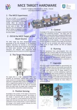
This report presents a comprehensive analysis of the MICE target's performance focusing on two bearing types: DLC and Vespel, evaluated during operation in the ISIS facility. Key findings include the reliability of Target 1 after over 155,000 actuation cycles and the rapid failure of Target 2, which used Vespel bearings. Issues surrounding dust production and performance variations across different actuation stages are highlighted, alongside calibration plots and diagnostic assessments aimed at improving future target designs. Future plans emphasize further testing and possible material upgrades.

MICE Target Report
E N D
Presentation Transcript
MICE Target Report Chris Booth (for target team) Sheffield 24th March 2010
History & Overview T1 – DLC bearings – running in ISIS >155k + 50 k actuations T2 – nominally identical to T1 Bearing failed rapidly T2.2 – like T1, improved QA Failed after ~80k actuations T2.3 – same stator & shaft as T2.2 New Vespel (polyimide) bearings Tested for >2.1M pulses in R78 Results of T1 running, T2.3 tests, and plans Chris Booth University of Sheffield 2
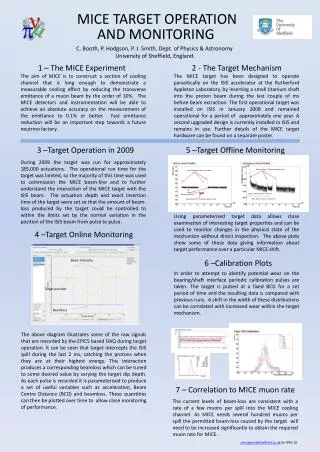
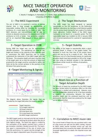
BCD (beam centre distance) Histograms(analysis by Paul Hodgson) T1 T2 distribution 3-4 times as broad Can be interpreted as a result of the target “sticking” Use the BCD histograms as a diagnostic to spot changes in target performance T2 Chris Booth University of Sheffield 3
T1 Calibration Plots • Running in ISIS allowed subject to • “target integrity tests” every 10k (formerly 5k) actuations • 400 pulses taken under standard conditions • Check for changes in behaviour • Inspections for dust every 50k actuations 0.4 mm
Conclusions for Target 1 Target continues to perform reliably No sign of significant change in BCD distributions No sign of dust production on view port Keep running! Chris Booth University of Sheffield 6
Status of Target 2 • T2 Vespel installed in R78 Jan 25th 2010 • DLC coated shaft (from T2.2) – Vespel bearings • Same stator body as previous T2 • Pulsed target continuously for 2.15×10⁶ pulses • Approx. one month of operation at ~1 Hz • Two short interruptions, chiller failed 1/2/2010, UPS failed 8/2/2010(!) • Neither problem associated with target mechanical performance • Target was deliberately stopped for inspection • Very little dust on view-port (~ daily photos) Chris Booth University of Sheffield 7
T2 BCD over month Early Mid Late Change over ~1 day 1×10⁶ pulses Start up period DAQ gain changes 720k s 1680k s
Look at BCD histograms in 3 regions Region 1 Early operation 120k – 360k pulses RMS 0.135 Asymmetric tail Region 2 Mid operation 720k – 960k pulses RMS 0.122 Asymmetric tail Region 3 late operation 1860k – 2100k pulses RMS 0.155 More symmetric with double peak structure but broader Chris Booth University of Sheffield 9
Comparison of BCD plots for T1 (DLC) and T2 Vespel T1 T2 Region 3 RMS of T2 Vespel is approximately twice that of T1 (Note different scales) Chris Booth University of Sheffield 10
T2 Acceleration over month Chiller failure UPS failure Test power off Chris Booth University of Sheffield 11
T2 Acceleration regions Late Mid Early Steady decline 848 to 838 ms-2 Increased variability Stable operation (838 ± 5) ms-2 720k s 1680k s Chris Booth University of Sheffield 12
Questions and Comments How would the target have performed if we had carried on pulsing ? Remember we arbitrarily stopped at 2.15 × 10⁶ pulses. Does the early period correspond to the target “bedding in” ? The mid period lasted approx. 1 million pulses where the target seemed to wear gradually. There was a reasonably rapid (1 day) change in performance after which the target parameters were (slightly) more variable. None of the variation seen above would compromise the normal target operation. The typical beam centre varies more than the target BCD. Chris Booth University of Sheffield 13
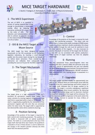
Disassembly & Inspection of Target 2(Jason Tarrant) • Target stopped after 2.16M actuations • Optics block removed & upper bearing exposed • Bellows removed & lower bearing exposed • Significant amounts of vespel dust, adhered to surfaces Chris Booth University of Sheffield 14
MICE Target First look • Disassembly – View of upper Bearing Little dust (polished flat) Most dust (rough flat) Dust On shaft, On bearing, On lock ring Rough flat Survey point Polished flat Amalgamated dust balls
MICE Target External face • Disassembly – View of lower Bearing Dust around bearing, lock ring removed Chris Booth University of Sheffield 16 Internal face
MICE Target • Observation – Dust • Amount • Most at upper bearing – esp. anti-rotate rough flat side • (Only one flat on shaft polished) • Amalgamated at bearings – scraped off • Location • Coated internal components, has escaped externally • How does it move / defy gravity? • Thrown off? • Electrostatic attraction? • Vibration movement? • When let up to air? • Attachment • Fixed – by what? Chris Booth University of Sheffield 17
Next Steps? • Reduce wear & dust production • Polished flats, burnished bearing faces • Possibly harder plastic (Duratron or Celazole) • Improved stator? (See below) • Observe when dust produced • Trap dust in catcher • Further tests start in May Chris Booth University of Sheffield 18
Stator QA • Is stator 2 different from stator 1? • Map field, with assistance of group at Diamond • Support rig built by Geoff Barber • Chiller, PSU, temperature interlocksready • Measurements to start this week • Stator 3 (unwelded) built in Sheffield • Permanent magnets will be (re-)measured • Modelling (Paul Smith, Owen Taylor?) to connect field asymmetries with off-axis forces Chris Booth University of Sheffield 19
Target Electronics & DAQ Upgrade • Phase 1 hardware complete,tested (Paul Smith) • USB interface to PC • Menu-driven interface in use(see screen shots) • GUI under development (James Leaver) • Control, monitoring, error notification • Much simpler interface (for non-experts!) • Plan to exercise thoroughly in R78 before installation in ISIS • Soak-test during next bearing evaluation Chris Booth University of Sheffield 20
Menu-driven controls Framework for terminal code programmed by James Leaver P J Smith - University of Sheffield
Prototype GUI for Target Control GUI screenshot provided by James. The exact layout may change a bit over the next weeks P J Smith - University of Sheffield
Summary Target 1 installed and operating well in ISIS Target 2 with plastic bearings performed reliably for >2M actuations Stopped for inspection, not due to failure Test & measurement programme for reducing and trapping dust Stators will be mapped to improve QA FPGA-based control essentially ready will give easier operation and enhanced monitoring Chris Booth University of Sheffield 23