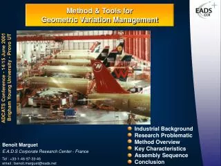
Industrial Background Research Problematic Method Overview Key Characteristics Assembly Sequence Conclusion
190 likes | 403 Vues
Method & Tools for Geometric Variation Management. ADCATS Conference - 14/15 June 2001 Brigham Young University - Provo UT. Industrial Background Research Problematic Method Overview Key Characteristics Assembly Sequence Conclusion. Benoît Marguet

Industrial Background Research Problematic Method Overview Key Characteristics Assembly Sequence Conclusion
E N D
Presentation Transcript
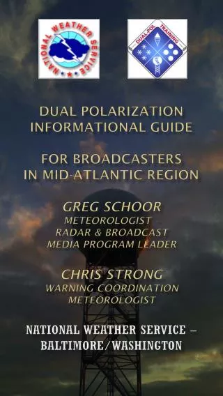
Method & Tools for Geometric Variation Management ADCATS Conference - 14/15 June 2001 Brigham Young University - Provo UT Industrial Background Research Problematic Method Overview Key Characteristics Assembly Sequence Conclusion Benoît Marguet E.A.D.S Corporate Research Center - France Tel : +33-1-46-97-33-46 email : benoit.marguet@eads.net
Industrial Background (I) Complex Product Extensive manufacturing organisation Structural Assembly High number of parts Various Assembly levels } Car Assembly Line Importance of Assembly Cost Aircraft manufacturing cost : 45% Assembly 30% Conversion 25% Material Aircraft Assembly Line Need to manage product’s assemblability
Industrial Background (II) Development cycle of aircraft sections Manufacturing Integration Design Assembly principles Sectionarchitecture Aircraft assemblySystem tests Airbus Section assemblySystem installations Design Tooling DesignDefinition Definition Drawings Tooling DefinitionManufacturing Assembly of workpackages Airbus or Suppliers Manufacturing of piece parts Manufacturing of assembly toolings Need to manage product’s assemblability as soon as possible during the development cycle
Problematic • How to improve product’s assemblability ? • By reducing assembly failures How to reduce assembly failures ? • Parts reduction • Geometric variation management Where to manage product variations ? How to control effect of variations on functional requirements? Sub-section assembly operation Geometric Variation Management Method (GEOVAR)
j7 j1 j8 j2 j4 j5 j3 j6 Method Overview GEOVAR : From product’s Key Characteristics to part’s specifications Design Principle Key Characteristics Product Structure Manufacturing Capabilities Assembly Sequence Part Specifications
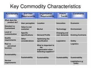
Product Key Characteristics (I) • Concepts • Functional requirements & related geometrical characteristics • are too numerous on complex product in order to manage all of them. • Need to focus attention of designers & manufacturers on what is really • important for the product. Definition “Product Key Characteristics are the geometrical features of component or sub-component whose variation has the greatest influence on the product function”. KC Identification Process • Functional • Requirement • Identification • (1) • Geometrical • Requirement • Identification • (2) • Product Key • Characteristics • Identification • (3)
Product Key Characteristics (II) • Functional Requirement Identification • Inputs : Preliminary Design, Product Structure • Outputs : Technical Requirements, Product Constraints • Tools : FAST Diagram, MIMIO 1
Correlation Matrix HOW Objective engineering specification WHAT Subjective customer preferences Relation Matrix How Much Tolerance Specification Product Key Characteristics (III) • Geometrical Requirements Identification • Inputs : Technical Requirements, Product Constraints • Outputs : Geometrical Requirements (nominal value and tolerance • level) • Tools : QFD Matrix Seat Rail Alignment QFD Matrix Geometrical Requirements 2
Product Key Characteristics (IV) • Key Characteristics Identification • Inputs : Geometrical Requirements, Assembly Process • Outputs : Hierarchical requirement level, PKCs • Tools : Risk Analysis PKC 3
Product Key Characteristics (V) • Benefits of exercise • Defines what is, and is not, important for the variation management. • Targets areas/features that need to be measured and monitored • (through SPC). • Helps designers to distribute tolerances & select appropriate datums. • Also • Clarifies of Design intent. • Promotes Concurrent Engineering. • Truly links Design, performance, manufacturing.
Assembly Sequence (I) • Problematic • Various assembly sequences are available for a single product. • All assembly sequence will have a different quality cost for the product. Question What assembly sequence will minimize impact of part’s variation on PKCs ? Assembly Sequence #1 Assembly Sequence #2
Assembly Sequence (II) • Concepts • Assembly Sequence analysis focus on PKCs (for variation impact). • Impact of part variation on PKCs depends on assembly sequence choice. • Selection of assembly sequence is made very early in the design cycle. Goal To analyze as soon as possible during the design cycle, all admissible assembly sequences in order to select the optimal one. Analysis Process • Mate & Contact • Identification • (1) • Propagation Chain • Identification • (2) • Worst Case & • Statistical • Tolerance • Analysis • (3)
Assembly Sequence (III) • Mate & Contact Identification (I) • Definition (D.E Whitney) • A mate is an assembly link that establishes constraints and dimensional relationships between part. • A contact is an assembly link that supports and fastens the part once it is located. • Property • Mate and Contact are related to the assembly sequence. • Geometrical variations flow from part to part through mates only. • Benefice • Easy to represent on a graph • Tool for variation propagation • analysis. M M Mate C C Cleat M Contact Stringer M C C C Cleat M Pannel M M 1
Assembly Sequence (IV) Mate & Contact Identification (II) Tools : Assembly Oriented Graph. AOG is a directed acyclic graphical representation of an assembly given a picture of the location dependencies of parts and surfaces. Each node represents assembly surface. Oriented arcs represent mates between two assembly surfaces. The arrow points on the positioned component. Oriented dotted arcs represent contacts between two assembly surfaces and dotted line represents geometrical conditions Upper Shell Right Upper Shell Left Assembly Sequence #1 Upper Floor KC Mate Lower Shell Lower Floor Contact Assembly surfaces Door Tool PKC 1
Assembly Sequence (V) • Propagation Chain Identification • Inputs : Assembly Oriented Graph, Key Characteristics • Outputs : Qualitative Assembly Sequence Analysis • Tools : Propagation Chain • Definition • A propagation chain is defined by all the mates necessary in order to perform a Product Key Characteristics. • Property • PKCs quality will be related • to the length of the • propagation chain. Upper Shell Right Upper Shell Left Upper Floor Lower Shell Lower Floor Door Tool Propagation Chain 2
Assembly Sequence (VI) • Tolerance Analysis • Inputs : Manufacturing Capabilities,Assembly Process, Geometric Characteristics, PKCs. • Outputs : Quantitative Assembly Sequence Analysis. • Tools • Available commercial software (Valisys, CeTol, 3DCS). • In house development (AnaTole). 3
Assembly Sequence (VI) • AnaTole Software • In house development based on TTRS, Variation Model (EADS C.C.R) and • Open Cascade (EADS MatraDatavision). • Benefits : • Easy to use without a deep knowledge of CAD system. • Very close to manufacturing and Design process. • Over-Constraint Detection and Analysis. • Statistical & Worst Case Tolerance Analysis. • Useable as soon as possible in the design cycle (wireframe geometry only).
Method Summary 1 To identify the major functional requirements 2 To translate the functional requirements into geometrical requirement 3 To identify the product’s Key Characteristics 5 To select the Mate / Contact assembly links 4 To select an admissible assembly sequence 6 To analyse the assembly sequence Are all geometrical conditions fulfill ? Is it possible to choose another assembly sequence ? Yes No To choose another assembly sequence To change design principle Yes No To improve Manufacturing capabilities Is it possible to improve the manufacturing capabilities Assembly sequence validated + tolerance specification Yes No
Conclusion & Future prospect • Need to manage tolerance from the functional requirement to ISO specification based on : • Product Key Characteristics • Assembly processes • Manufacturing Capabilities • Definition & Deployment of a Variation Management Method • Useful for complex product like aircraft. • Used as soon as possible during the design process. • Allowing to select the optimal assembly sequence. • On going Works • Take into account flexible parts in the method • Automatic assembly sequence planning • & analysis. • Wide deployment of the method.