Download
1 / 26
260 likes | 437 Vues
RTSX-S and RTSX-SU Reliability Test Vehicles. Daniel K. Elftmann Director Product Engineering Richard Katz Head Grunt Office of Logic Design Igor Kleyner Deputy Grunt Office of Logic Design September 8 th , 2004. Background. Background

E N D
RTSX-S and RTSX-SU Reliability Test Vehicles Daniel K. ElftmannDirector Product Engineering Richard Katz Head Grunt Office of Logic Design Igor Kleyner Deputy Grunt Office of Logic Design September 8th, 2004
Background • Background • In 2003, some customers reported clusters of failures • Customer failures had some common factors • Stressful designs • I/O and/or power supplies exceeding datasheet limits • Failures occur early in device life • Actel investigation indicated isolated programmed antifuses were failing to a higher impedance state • Industry investigation • Actel working closely with Industry Tiger Team (ITT) led by The Aerospace Corp. • Participants include Lockheed Martin, Boeing, General Dynamics, Northrop Grumman Space Technology, JPL, NASA • A series of experiments are being conducted to investigate the customer failures • Remainder of presentation describes the two different Test Vehicles being used for the following experiments • Industry Tiger Team Design • NASA Test Design
Industry Tiger Team Design 1,146 Stage Slow Ring Oscillator • Synchronized Reset input assures clean startup of slow ring oscillator • Delta Read & Record must be done via frequency measurement • No mechanism to break ring and measure delay directly • Zoom Debug feature • Allows for enhanced isolation of delays during debug only • Long oscillator frequency stabilization time of ~15 minutes at startup
Industry Tiger Team Design 140 Bit I/O Shift Register • Independent controls to set Pattern generator toggle rate for internal R-Cells • 16 unique patterns possible, with range of toggle rates (more later) • Clock generated via internal 15 stage ring oscillator (~50MHz) • Dedicated Startup Synchronization circuitry for IO_clock domain • IO_Monitor indicates pass/fail • On-chip self-checking circuitry detects and latches detected errorsNote: not all errors are detectable by self-test
Industry Tiger Team Design Ring Oscillator • Ring Oscillator instantiated twice • 1st drives Array SR, 2nd drives I/O SR • Additional delay stage inserted in Array oscillator to keep two oscillators out of sync • Ring Oscillators frequency dependent on Temperature & VCCA voltage • Ring Oscillators NOT recommended for flight designs
Industry Tiger Team Design Shift Enable Control • Independent Shift Enable circuits instantiated in each of the 2 sequential blocks to pace R-Cell toggling • ShiftEnable_n fanout = 16 • R-Cell U0 fan out managed via register replication • Both Array shift register &I/O shift register blocks set by same input configuration pin settings:
Industry Tiger Team Design I/O Weave Shift Register • I/O Weave block three modes of operation • Mode 1: I/O Bypass (OE=‘0’ TOG_n=‘X’) • Operates as shift register bypassing the I/Os thru 2-1 multiplexers • No I/Os toggle and are tri-stated
Industry Tiger Team Design I/O Weave Shift Register • I/O Weave block three modes of operation • Mode 2: I/O Weave (OE=‘1’ TOG_n=‘1’) • Operates as shift register toggling I/O pad at pattern generator defined rate • Signal takes path thru output buffer to the pad and back into input buffer • I/O toggle rate controlled by Pattern Generator
Industry Tiger Team Design I/O Weave Shift Register • I/O Weave block three modes of operation • Mode 3: All I/O Toggle (OE=‘1’ TOG_n=‘0’) • Simultaneously switches all I/Os from 0 to 1 then 1 to 0 • Pattern follows shift register chain enabling pattern checker to detect errors at any point in chain • Register n+1 <= !n • Simultaneous 100% I/O Toggle Rate
Industry Tiger Team Design 707 Bit Array Shift Register • Array shift register has independent controls to set Pattern generator toggle rate for internal R-Cells • Options for the Pattern Generator identical to I/O Shift Register Pattern Generator • Typical setting for Simultaneous Switching Registers (SSR) set at 12.5% • Clock generated via internal 16 stage ring oscillator (~50MHz) • Dedicated Startup Synchronization circuitry for A_Clock domain • A_Monitor indicates pass/fail • On-chip self-checking circuitry detects and latches detected errorsNote: not all errors are detectable by this self-test
Industry Tiger Team Design Aerospace Experiments Colonel Test Project 4b1 Temp = ~40°C VCCA= 2.5V RT54SX32S MEC with “old” algo ~500 parts Project 7 Temp = ~40°C VCCA= 2.5V Project 4b2 Temp = ~40°C VCCA= 2.5V 600 hrs 1000 hrs + General Test RT54SX32S MEC with “new” algo 330 parts Project 4b2 Temp = ~40°C VCCA= 2.5V 83 parts RT54SX32S MEC with “old” algo 83 parts Project 4b2Temp = 85°C VCCA= 3.0V 1000 hrs +
Header Board DUT NASA Design Header Bd. Clock & Reset Driver • NASA Office of Logic Design (OLD) designed and built solder in card to Burn-in Board (BIB) to provide clock and reset to 8 Devices Under Test (DUT) • Card solders into BIB configuration socket locations • Clocks for DUTs in each column can be controlled to run 180° out of phase • Clocks can be driven up to 64MHz • Jumper selectable clock dividers available on Header Board • HCLK, CLKA, and CLKB frequency independently settable
NASA Design 1,236 Stage Delay Line • Configuration lines select input to delay line during operation • Synchronized Reset input insures clean startup • Direct delay delta read & record measurement possible via Delay_in • No free running oscillator & related self-heating thermal effects, therefore no startup stabilization issues • Allows for more accurate delay measurements • Zoom feature removed as un-needed, Action Probe circuitry sufficient for debug
NASA Design 144 Bit I/O Shift Register • Changes • Utilizes HCLK vs. 15 stage internal ring oscillator • Industry Tiger Team design does NOT utilize the HCLK resource • HCLK driven by NASA header board add-on card • Dedicated Reset Synchronization circuitry for HCLK clock domain • Increased fan out of Shift Register Enable nets from 16 vs. 29 • Exceeds maximum fan out allowed (24) in Designer Software by 20% • Number of I/Os 143 vs. 139 • 78 configured for 5V CMOS, remainder 5V TTL; Industry Tiger Team design all TTL
NASA Design 621 Bit Array Shift Register • Changes • Utilizes CLKA vs. 16 stage internal ring oscillator • CLKA driven by NASA header board add-on card • Increased fan out of Shift Register Enable nets from 16 vs. 29 • Exceeds maximum fan out allowed (24) in Designer Software by 20% • Shift register R-Cells manually placed to improve utilization of Long Vertical Tracks (LVT) and Long Horizontal Tracks (LHT) • Array_out added to increase observability at tester • Number of bits 621 vs. 707
NASA DesignFinal Design Summary • Utilization Post-Combiner device utilization: SEQUENTIAL Used: 1080 Total: 1080 (100.00%) COMB Used: 1800 Total: 1800 (100.00%) LOGIC Used: 2880 Total: 2880 (100.00%) (seq+comb) IO w/ Clocks Used: 168 Total: 170 (78 CMOS) (89 TTL) CLOCK Used: 2 Total: 2 HCLOCK Used: 1 Total: 1 • Fan out • 23 nets have fan out of 29 • 1 net with fan out of 28 • Timing Analysis • Maximum frequency (@ 125C, VCCA = 2.25V, VCCI = 4.5V, Speed –1) • Array Clk => 72MHz • IO Clk => 71MHz • Hold time analysis (@ -55C, VCCA = 2.75V, VCCI = 5.5V, Speed –1) • Shortest path slack => 0.51ns • NASA design bounds user applications better than Industry Tiger Team design
NASA Experiments Parts to be tested in 500 hour steps Stress levels increased for each step. Voltage, # SSOs, amount of SSU, time Internal circuit loading fixed at 120% of max load Each step is 250 hours of HTOL followed by 250 hours of LTOL Test Protocol HOT RT54SX32S MEC “Modified New Algo” 300 parts Increasing VCCA/VCCI Voltage Increasing SSO Increasing SSU Increased time Project KH1 Temp = 125°C VCCA= 2.75V RTSX32SU UMC 300 parts 250 hrs COLD RT54SX32S MEC “Modified New Algo” Increasing VCCA/VCCI Voltage Increasing SSO Increasing SSU Increased time 300 parts Project KC1 Temp = -55°C VCCA= 2.75V RTSX32SU UMC 300 parts 250 hrs
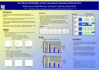
ITT Design Actel RTSX-SU (UMC) Data set • This data set includes the following for RTSXS-U: • 2 sets of experiments were completed (P7, P4B2) • RTOL = Room Temperature Operating Life • TC = Temperature Cycle (-65°C to 150°C)
ITT Design P7 Data • Configuration Details: • No I/O’s toggle, Array toggle rate = I/O toggle rate = 12.5% • 3 monitor pins toggling - Visual readout using LED • Undershoot less than -0.4V
ITT Design P4B2 Data • Configuration Details: • I/O toggle rate = 50% (70 I/Os), Array toggle rate = 12.5% • ~2V undershoot
NASA/Actel Team • NASA • Igor Kleyner • Rich Katz • Actel • Manish Babladi • Marco Cheung • Paul Louris • Minal Sawant • Dan Elftmann