Download
1 / 8
80 likes | 249 Vues
Lecture #15 EGR 277 – Digital Logic. Reading Assignment: Chapter 5 in Digital Design, 3 rd Edition by Mano.

E N D
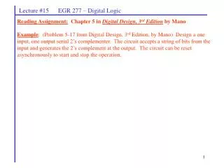
Lecture #15 EGR 277 – Digital Logic Reading Assignment: Chapter 5 in Digital Design, 3rd Edition by Mano Example: (Problem 5-17 from Digital Design, 3rd Edition, by Mano) Design a one input, one output serial 2’s complementer. The circuit accepts a string of bits from the input and generates the 2’s complement at the output. The circuit can be reset asynchronously to start and stop the operation.
Lecture #15 EGR 277 – Digital Logic • Recall that there are two methods covered in Chapter 5 for designing sequential circuits: • 1) Excitation table method (already covered) • 2) State equation method • Before the state equation method is covered, two related topics must be covered: • state equations • flip-flop characteristic equations State Equations A state equation is an equation for the next state of a flip-flop. It has the form: Q(t + 1) = (Boolean expression involving present states and inputs) The state equations are simply formed using the “Next State” shown in the state table.
0 1 0 1 0 4 1 0 1 1 2 3 0 1 0 Lecture #15 EGR 277 – Digital Logic Example: Find the state equations for the state diagram shown below.
Lecture #15 EGR 277 – Digital Logic Flip-flop characteristic equations Flip-flop behavior has been expressed so far using truth tables or excitation tables. The next state (output) of a flip-flop can also be described algebraically using a flip-flop state equation or flip-flop characteristic equation. Example: Develop the flip-flop characteristic equation for a JK flip-flop.
Lecture #15 EGR 277 – Digital Logic Example: Develop flip-flop characteristic equations for SR, D, and T flip-flops.
Lecture #15 EGR 277 – Digital Logic Designing Sequential Circuits using State Equations – Procedure 1. Form the state table. 2. Develop the state equations from the state table. 3. Determine the type of flip-flop to be used. 4. Manipulate the state equation into the form of the characteristic equation for each flip-flop. This will yield the flip-flop input expressions. • Notes: • It is easiest to design by state equations using D flip-flops. • Many PLD’s only support D flip-flop designs, so state equations are very useful. • JK flip-flop designs will yield the simplest circuits in general. • Designing circuits by the excitation table method method and by the state equation method should yield the same results.
Lecture #15 EGR 277 – Digital Logic Example: Design a modulo-7 counter by the state equation method using: A) D flip-flops
Lecture #15 EGR 277 – Digital Logic Example: Design a modulo-7 counter by the state equation method using: B) JK flip-flops.