Download
1 / 23
230 likes | 320 Vues
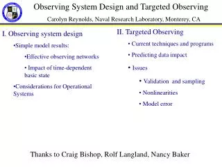
Near IR FF design including FD and longer L* issues. Andrei Seryi (SLAC) October 16, 2008 CLIC 08 Workshop. ILC IR configuration & stability. Intratrain feedback within 1ms train No active mechanical stabilization of FD FD jitter tolerance about hundred nm. (old location).

E N D
Near IR FF design including FD and longer L* issues Andrei Seryi (SLAC) October 16, 2008 CLIC 08 Workshop
ILC IR configuration & stability • Intratrain feedback within 1ms train • No active mechanical stabilization of FD • FD jitter tolerance about hundred nm (old location) Intratrain feedback kicker
CLIC IR discussion… • In CLIC, with 1nm beam size, and 150ns train, has to use all possible options to provide stability • Can’t afford ~50ns trip-around time of intra-train feedback IP QD0 QF1 Detector Intratrain feedback kicker
CLIC IR discussion… • First MUST-DO is to minimize the trip-around time, thus move kicker and BPM closer to IP • Locating centers 2m from IP give irreducible delay of 12ns • With total latency of ~25ns, can already have ~6 iterations of feedback • Feedback electronics may need to be closer to IP too IP QD0 QF1 Detector Intratrain feedback kicker and BPM Achieved latency of FONT3 analog electronics ~13ns (P.Burrows et al).
CLIC IR discussion… • Placing feedback electronics (perhaps need to be shielded, from pairs and radiation) may push the FD out • FD is still supported by detector which is likely to be ~30nm stable • With FD half way out, tempting to consider removing it from detector entirely, and exploring advantages of such change IP QD0 QF1 Detector Intratrain feedback kicker and BPM Feedback electronics and its shielding
Detector is a noisy ground Measured ~30nm relative motion between South and North final triplets of SLC final focus. The CLIC or ILC detector may be designed to be more quiet. However present state of detector engineering does not allow relying on that.
Luminosity dependence on L* for ILC • For nominal energy, in some range of parameters and geometries the loss of luminosity is slower than linear with L* • Due to possibility to open extraction apertures and not to tighten the collimation depth • Based on a model that include assumptions about beam jitter, collimation wakes, etc. • Specific studies for CLIC parameters need to be done • Tentative dependence of luminosity on L* for ILC parameters • Reduced by ~5-10% for L* 3.5m => 4.5m • Reduced ~factor of two for 3.5m=> 7.0m at min energy and ~25% at max energy
CLIC IR discussion… • At high energy, the SR in FD is very important, and with doubled L*, to keep SR effects small, one would also have to lengthen the quads • Long quads may need to be naturally split to independent pieces • Split quads in N pieces may give 1/N0.5 improvement of stability IP QD0 QF1 Detector Intratrain feedback kicker and BPM Feedback electronics and its shielding
CLIC IR configuration • After all these steps, the changed concept of CLIC IR looks like this: interferometer network IP QD0 QD0 QD0 QD0 QF1 QF1 QF1 QF1 tunnel floor ~3nm stable stabilization supports Detector Intratrain feedback kicker and BPM Feedback electronics and its shielding
New CLIC IR – advantages • Reduced feedback latency – several iteration of intratrain feedback over 150ns train • FD placed on tunnel floor, which is ~ten times more stable than detector – easier for stabilization interferometer network IP QD0 QD0 QD0 QD0 QF1 QF1 QF1 QF1 tunnel floor ~3nm stable stabilization supports Detector • Not limited by sizes of stabilization system or interferometer hardware Intratrain feedback kicker and BPM 2m from IP Feedback electronics and its shielding • Reduced risk and increased feasibility • May still consider shortened L* for upgrade
What is achieved / Sizes of hardware ~0.3m R.Assmann et al, Stabilization with STACIS give ~10 reduction of tunnel floor vibration P.Burrows et al, FONT3 demonstrated latency of 23ns, including 10ns of irreducible time-of flight Monitoring, Alignment&Stabilisationwith highAccuracy D.Urner et al, MONALISA interferometer system for ATF2 final doublet: space availability matters ~2m
FF design for L*=8m • To support the long L* idea, started to look at BDS design with L*=8m for CLIC beam and E=3TeV CM • Start from NLC BDS • reduce and optimize dispersion • lengthen and optimize FD • retune the optics to cancel aberrations • (BDS length or location of elements was not changed in comparison with initial NLC BDS) • (Did not optimize or evaluate collimation system survivability) • Design look promising • (after just ~week of efforts) • Luminosity somewhat lower that nominal (~80%) • Further optimization may bring “double L* BDS” close to nominal performance
L*=8m version: CLIC_LSTAR17.mad Designed for 3TeV CM, IP emittances = (660/20) nm IP betas = (6.9/0.068) mm
L*=8m version: CLIC_LSTAR17.mad Final doublet at 3TeV CM: QD0: 213 T/m QF1: 72 T/m (Sextupoles need to be lengthened and reoptimized)
L*=8m version: CLIC_LSTAR17.mad Energy bandwidth (MAD) Major remaining aberrations are Uxx’x’x’ and Wyx’x’y’d So far they limit achievable IP beam size
L*=8m version: CLIC_LSTAR17.mad • Evaluation: (with several codes) • Transport: aberrations • Turtle: tracking (without SR effects) • Dimad: tracking • without SR • with SR in bends • with SR in bends and all other magnets • (looking at Dimad tracking, optimize FD length and the value of dispersion in FF and in Collimation) • Guinea-pig beam-beam taking Dimad tracked beam with all SR included
L*=8m version: CLIC_LSTAR17.mad • Evaluation: • Dimad: tracking with SR in all magnets, versus rms energy spread: Y-bandwidth affected by remaining aberration of 4th order Wyx’x’y’d Can be further improved
L*=8m version: CLIC_LSTAR17.mad • Evaluation (continued): • Track (with all SR), GP, and study Luminosity and L(in 1%) versus IP beta-function • So far achieved: • L(1%)= 1.35e34 cm-2s-1 for nominal (6.9/.068) IP b • L(1%)= 1.60e34 cm-2s-1 for (13/.1) IP betas • or 80% of nominal luminosity in 1% peak en sge bex bey sx0 sy0 Tsx Tsy Tsx*Tsy D0sx D0sy D2sx D2sy D4sx D4sy BTD:1500 3.5 0.0069 6.8e-005 0.039388 0.00068067 0.075213 0.001446 0.00010876 0.07781 0.001218 0.08794 0.001479 0.08746 0.001739 Dimd, G-P: sxy=6.713e-005 Ltot=2.9588e+034 L(in 1%)=1.3561e+034 BTD:1500 3.5 0.013 0.0001 0.054064 0.00082543 0.069853 0.001216 8.4941e-005 0.06958 0.00109 0.07642 0.001303 0.07647 0.001478 Dimd, G-P: sxy=5.6072e-005 Ltot=3.5424e+034 L(in 1%)=1.6018e+034 Use Luminosity equivalent spot size both from Turtle and Dimad
L*=8m version: CLIC_LSTAR17.mad GP spectrum, Dimad tracking with SR. (13/0.1)mm IP betas. (Lumi shown is per bunch crossing)
L*=8m version: CLIC_LSTAR17.mad • Evaluation (continued): • For IP betas of (13/0.1mm): linear IP sizes, x y : 54.06 0.825 nm with aberrations (dE/E=0.35%) : 69.58 1.090 nm (128.7 132.1%) (+^2: 81 86%) with SR in bends only : 76.42 1.303 nm (141.4 157.8%) (+^2: 58 86%) with SR in all magnets : 76.47 1.478 nm (141.4 179.1%) (+^2: 0 85%) • => contributions to Y size at IP from • aberrations • SR in bends (producing dE/E and e) • SR in Final Doublet • are about equal • (+^2 == added in quadratures)
L*=8m and Collimation • The present BDS with L*=3.5m has Final Doublet with aperture radius r~4mm • The new BDS with L*=8m will have FD (SC) with aperture r~10mm (still smaller that Rvx) • => collimation depth will not be more tight. • good.
Summary • BDS with L*=8m may be feasible for CLIC, even for 3TeV CM • Luminosity (in 1%peak) is ~80% of nominal 2E34 • Further optimization possible • (but also errors in BDS need to be included) • Advantages of doubled L* • The FD stability may be claimed to be feasible now, with present technology that was already demonstrated • (FD magnetic center stability is a separate issue ~independent on L*, and needs to be verified in any case) • (Compare: CLIC FD stability requirements for L*=3.5m are extremely challenging) • Plus, much simpler MDI, easier FD design, no need for antisolenoid, etc