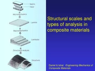
Composite Structural Analysis and Design Issues
Composite Structural Analysis and Design Issues . ME 7502 – Lecture 14 Dr. B.J. Sullivan. Finite Element Analysis of Composite Structures. Lamina stress analysis in FEA of composites Considerations in selection of element types Modeling individual layers with orthotropic elements

Composite Structural Analysis and Design Issues
E N D
Presentation Transcript
Composite Structural Analysis and Design Issues ME 7502 – Lecture 14 Dr. B.J. Sullivan
Finite Element Analysis of Composite Structures Lamina stress analysis in FEA of composites Considerations in selection of element types Modeling individual layers with orthotropic elements FEA model construction Boundary conditions in FEA of composite plates and shells Thermal and Thermo-Structural Analysis Methods Assessment of Calculated Stresses and Strains Determination of Allowable Stresses and Strains Calculation of Margins and Safety FEA Assessment of Delamination Growth in Composite Structures
Lamina stress analysis in FEA of composites Some public domain FEA codes have at least the capabilities a), b) and c) above; Capability d) can be user-dependent; i.e., the user may wish to be very specific about how lamina level stresses are combined within a failure criterion to make judgments regarding failure
Lamina stress analysis in FEA of composites ANSYS, ABAQUS, NATRAN public domain FEA codes all have laminated composite plate and shell elements Required input includes: Lamina (ply) properties in local material directions Orientation of ply relative to laminate (global) coordinate direction Lamina (ply) thickness Lamina failure algorithm (e.g., Hashin, Puck, etc.) and associated parameters Output features: Stresses in each ply in local material axes Stress contour plots within plies across continuous elements Margin of safety contour plots within plies across continuous elements, based on failure criterion and its parameters
Considerations in Selection of Element Types • Three basic questions in element selection: • Should elements be represented by plate elements or solid elements? • Plate elements do a good job of capturing bending behavior and will require far fewer elements to simulate response • Solid elements provide a much better assessment of the interlaminar stresses • If plate elements are selected, should homogenous orthotropic properties be used, or should individual ply properties be used? • Homogenous orthotropic properties require single plate/shell elements through the thickness • Use of individual ply properties in FE analysis requires use of layered plate/shell elements through the thickness • Should elements with transverse shear deformation be employed?
Considerations in selection of element types Laminate approximated by homogeneous orthotropic plate properties (average properties throughout)
Considerations in selection of element types Laminate approximated by homogeneous orthotropic plate properties (average properties throughout)
Use of Elements with Transverse Shear Deformation • Most general purpose FEA codes provide plate and shell elements with transverse shear capability • As we have seen, this can be an important aspect of composite structural analysis in two cases: • The ratio of in-plane Young’s modulus to through thickness shear modulus is relatively large (in some cases as low as 5; for metals, E/G < 3 is typically) • The span-to-thickness ratio is small (~25 or less) • If you are not sure if shear deformation is important, try to perform identical analyses with and without this effect • Near identical results will indicate shear deformation is not important • Different results will indicate the importance of this feature in your analysis
FEA Model Construction • Typical FEA model construction practice is not substantially different from metallic parts • Shell / flat plate elements for thin gauge members, e.g. facesheets • 3D solid elements for thicker parts, e.g. solid leading edge materials and core material of sandwich structure components • 3D solids or 3D beam elements for longerons and ribs
FEA Model Construction • One area of difference between FEA analysis of metallic parts and FEA analysis of composite parts is that more submodels are needed to accurately assess responses of composite parts, since interlaminar strengths of these materials are typically low • This is particularly true for refractory (e.g., Carbon-Carbon and Ceramic Matrix Composites) • Submodeling effort is accomplished by creating a smaller model of the components where overstress in the full scale model is calculated • More elements through the thickness and better aspect ratio elements used
Example of FEA Submodel • Cut Boundary Interpolation is performed by taking the resulting displacements from the full scale model that occur at the cut boundary of the sub model and applying them to the sub model (shown with bright blue arrows in picture on right) • Submodel temperatures are applied using a Body Force interpolation, where temperatures are taken from the full scale model and applied to the submodel Submodel shown with applied temperatures and displacements from full scale model Submodel is composed of volumes outlined in orange.
Boundary Conditions in FEA of Composites Here, the pressure load p is symmetric about both X and Y axes • For isotropic plates and shells, we frequently use symmetry B.C.’s to avoid having to analyze the entire body • For example, a plate under a load symmetric about one or two axes parallel to the edges can frequently be analyzed with a reduced model by employing symmetry B.C.’s:
Boundary Conditions in FEA of Composites For loads and edge B.C.’s symmetric about both X and Y axes, an isotropic plate can be analyzed with a quarter segment and the following B.C.’s: where Edge #1 could be simply-supported (uZ = qX = qZ = 0) or clamped (uZ = qX = qY = qZ = 0) and Edge #2 could be simply-supported (uZ = qY = qZ = 0) or clamped (uZ = qX = qY = qZ = 0)
Boundary Conditions in FEA of Composites • For composite plates, the elements of the A, B and D matrices must be examined before deciding if symmetry B.C.’s such as those used above can be employed to make the model smaller • For example, even if the load and edge B.C.’s are symmetric about the X and Y axes, if the laminate has shear-extensional coupling (i.e., if A16 and A26 are not zero), then symmetry B.C.’s are the type shown above cannot be used, since • uY is not zero across the X-axis cut, and • uX is not zero across the Y-axis cut • If the laminate has no shear extensional coupling (i.e., if A16 = A26 =0) but does have bending twisting coupling (i.e., if D16 and D26 are not zero), then qZ is not zero across either axis cut, so that here again symmetry B.C.’s could not be used • In either case, the entire plate would have to be analyzed.
Boundary Conditions in FEA of Composites • The same conclusion can be drawn for plates with bending-extensional coupling (i.e., non-zero Bij coefficients) since any loads causing bending would mean • uY would not be zero across the X-axis cut, and • uX would not be zero across the Y axis cut • Suppose we have a balanced and symmetric laminate (A16 = A26 = Bij = 0) making up a plate which has loads and edge boundary conditions symmetric about one or both axes • Typically, we will have bending-twisting coupling (i.e., D16 and D26 will be non-zero), so that, strictly speaking, the model cannot be made smaller by employing symmetry B.C.’s across the X-axis or Y-axis cuts • Practically speaking, however, if there are many plies and the plies are well dispersed within the laminate, the magnitude of D16 and D26 relative to the other Dij will be small • In these cases we treat the laminate as if it were specially orthotropic and employ symmetry B.C.’s
Boundary Conditions in FEA of Composites Examples of laminate stack-ups and associated bending-twisting coupling coefficients: The greater the number of plies and the more dispersed the plies within the laminate, the smaller the D16 and D26 coefficients relative to the others, the better the representation of the plate as Specially Orthotropic, and the more appropriate the use of symmetry B.C.’s if loads and edge B.C.’s are themselves symmetric
Boundary Conditions in FEA of Composites • The same concepts apply to the analysis of composite shells • For example, the half-symmetry model of the cylindrical shell shown on the next page would not be appropriate if • The laminate contained shear-extensional coupling, or • If loads causing bending were present and there was substantial bending-twisting coupling
Thermal and Thermo-Structural Analysis Methodology • In assessment of composite components on vehicles subjected to time-varying thermal loads, both transient heat transfer and thermal stress analyses are performed • Stress analyses typically require greater discreteness in the FE grid than what is required for thermal analyses • Displacement, strain and stress spatial gradients are typically much greater than spatial temperature gradients • Nevertheless, same FE model is used for both transient heat transfer and thermal stress analyses • Elements selected for the FE analyses must be capable of switching from thermal to stress types
Thermal and Thermo-Structural Analysis Methodology • Transient heat transfer analyses must usually be performed for some period of time beyond the cruise/re-entry period • Thermal soak must be permitted to occur • Highest temperatures in thermal protection system (TPS) components often do not occur until after “wheel stop” Wheel Stop Period of thermal soak may actually be 2-3 times as long as period of aerothermal heating
Thermal and Thermo-Structural Analysis Methodology • “Snap shot” thermal stress analyses are performed for a few discrete times of flight • Times corresponding to peak thermal gradients • These times will lag time of peak gradient(s) in aero-thermal heating • Times corresponding to peak temperatures of different materials in CMC components • These times will lag time of peak aero-thermal heating Candidate times for thermal stress analyses
Thermal and Thermo-Structural Analysis Methodology • Measured stress-strain curves of composite material used in structural components will dictate type of analysis performed • Non-linear response requires nonlinear material analysis and strain allowable assessments • Linear response permits linear material analysis and allowable stress assessments
In Plane Stress σx (6.3ksi) In Plane Stress σy (6.0ksi) ILT and ILS are localized stresses σz (6.0ksi) Assessment of Calculated Stresses and/or Strains • Peak stresses or strains appearing on FEA contour plots are not appropriate for realistic assessment of component performance • When failure is initiated within a composite test specimen, the initial failure occurs over a region containing several (3-5 at a minimum) textile unit cells • A textile unit cell is defined as the “smallest volume of the fiber reinforcement containing all unique fiber orientations in the preform” (i.e., longitudinal, lateral, and through thickness) In-plane stress in torque tube of flaperon EDU resulting from mechanical loading Stress Contours in access panel of flaperon EDU resulting from mechanical loading
Assessment of Calculated Stresses and/or Strains • Accordingly, in the comparison of FEA calculated strains or stresses, an average of any given strain or stress component over a volume of at least three (3) unit cells should be compared to the measured failure strain or stress of the material • This approach definitely makes the structural analysis more time consuming One textile unit cell
Assessment of Calculated Stresses and/or Strains Photomicrographs of Composites and Definition of Unit Textile Cells One textile unit cell
Generation of design properties through material property testing How are the thermo-elastic properties used in the material models of the composite FE analyses determined? How are the composite strength or strain-to-failure values measured? How are the measured strengths used to define allowable values for the comparison with calculated stresses/strains?
Design Properties • Most basic element of design properties database is material thermo-elastic properties themselves • Young’s moduli (tension and compression) • Axial shear modulus • Poisson’s ratios • Coefficients of thermal expansion • Thermal conductivities • Thermo-elastic moduli and thermal conductivities are typically temperature-dependent
Design Properties • For full three-dimensional orthotropic materials, all properties (e.g., through thickness Young’s and shear moduli) cannot be measured • Micromechanics models are correlated using measurable data and then used to predict properties that cannot be measured • Temperature-dependent strengths are frequently measured at same time as moduli • Axial tensile and compressive • In-plane shear strengths • Through thickness strengths (tensile, compressive, shear) are measured alone
Tension Specimen This specimen is used to measure the composite in-plane axial tensile modulus and strength
Compression Specimen This specimen is used to measure the composite in-plane axial compressive modulus and strength
Rumanian Shear Specimen This specimen is used to measure the composite in-plane axial shear modulus and strength
Double Notch Shear Specimen This specimen is used to measure the composite through thickness or interlaminar shear strength
Curved Beam Specimen This specimen can be used to measure the composite through thickness tensile strength
Thermal Expansion Specimen This specimen can be used to measure the composite in-plane coefficients of thermal expansion (CTE)
Design Properties • Definition of A-basis allowable property: • Design property for which there is a 95 percent confidence that 99 percent of the tested material samples will exceed this value • B-basis allowable property defined as property for which there is a 95 percent confidence that 90 percent of the tested material samples will exceed this value • Guidelines for composite material test programs to achieve A-basis or B-basis allowable properties are provided in MIL-HDBK-17
Allowable Material Properties • A statistical software package known as STAT17, a by product of the MIL-HDBK-17 Working Group, is available for calculating A-basis and B-basis allowable properties from measured material property test data • A-basis and B-basis properties for polymer matrix composites used in military aircraft exist • Reinforced Carbon-Carbon used on Space Shuttle is the only refractory composite material for which A-basis properties exist • B-basis properties for specific material properties exist for ACC-6 and CVI C/SiC
Other Critical Design Properties • Tensile strength of specimens with butt-joint plies • Strength of notched specimens (i.e., specimens containing open holes) • Strength of specimens containing loaded holes • Bearing strength • Net tension and/or compressive strength • Shear tear-out strength
Calculation of Margins of Safety • Margins of safety (MOS) are used to quantify the state of stress or strain relative to design allowable values • Margins of safety must be calculated using either calculated stresses or strains • In expression below, substitute eAllowable and eActual for corresponding stress quantities, if strain allowable design approach is used • Typically for composite stresses calculated via FEA, the MOS for one component at a time is calculated
Calculation of Margins of Safety • Example of a typical MOS table: • This approach ignores potential adverse affects of stress or strain interaction
Interlaminar Strain Interaction Material characterization testing to define interaction curves for all relevant components and at all temperatures of interest can be costly
Comments on Load Factors and Factors of Safety Load factors and factors of safety are used to amplify loads and calculated stresses, respectively, prior to determining MOS values Load factors are a reflection of the degree of uncertainty in the applied loads Factors of safety are intended to reflect the degree of uncertainty in the calculated stresses due to the complexity of the structure and/or the uncertainty in the math model representation of physical structure Typical factors of safety for composite structures (from NASA-STD-5001: Structural Design and Test Factors of Safety for Spaceflight Hardware)
Hot Structure / TPS ComponentsLoad Factors and Factors of Safety * 1.5 if tested; 2.0 if not tested