Download
1 / 20
200 likes | 264 Vues
Structural design is primary aspect of Civil Engineering. The very basis of construction of any building, residential house or dams or bridges, culverts, canals etc. is designing. Structural engineering has existed since humans first started to construct their own structures. The foremost basic in structural engineering is the design of simple basic components and members of a building viz., Slabs, Beams, Columns and Footings. In order to design them, it is important to first obtain the plan of the particular building. Thereby depending on the suitability plan layout of beams and the position of columns are fixed. Thereafter, the loads are calculated.Once the loads are obtained, the component takes the load first i.e. the slabs can be designed. Designing of slabs depend upon the type of slab and end conditions and loading. Then the beams are designed thereafter the columns. Most of the columns designed in this project are axially loaded columns with uniaxial bending Finally the footings are designed based on the loading from column and also the soil bearing capacity value of that particular area. Most importantly, the sections must be checked for all the four components with regard to strength and serviceability Potharaboyena Vinay | Kurimilla Srilaxmi "Structural Analysis and Design of Structural Elements of A Building" Published in International Journal of Trend in Scientific Research and Development (ijtsrd), ISSN: 2456-6470, Volume-2 | Issue-3 , April 2018, URL: https://www.ijtsrd.com/papers/ijtsrd11237.pdf Paper URL: http://www.ijtsrd.com/engineering/civil-engineering/11237/structural-analysis-and-design-of-structural-elements-of-a-building/potharaboyena-vinay<br>

E N D
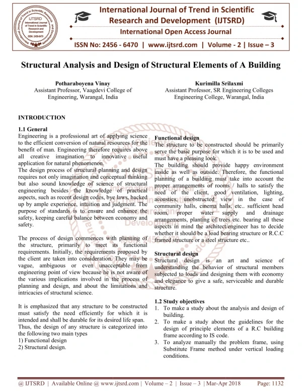
International Research Research and Development (IJTSRD) International Open Access Journal International Journal of Trend in Scientific Scientific (IJTSRD) International Open Access Journal ISSN No: 2456 ISSN No: 2456 - 6470 | www.ijtsrd.com | Volume 6470 | www.ijtsrd.com | Volume - 2 | Issue – 3 Structural Analysis and Design of Structural Elements of A Building Structural Analysis and Design of Structural Elements of A Building Structural Analysis and Design of Structural Elements of A Building Potharaboyena Vinay Assistant Professor, Vaagdevi College Engineering, Warangal, India Kurimilla Srilaxmi Kurimilla Srilaxmi Vaagdevi College of India Assistant Professor, SR Engineering Colleges Engineering College, Engineering Colleges Warangal, India Functional design The structure to be constructed should be primarily serve the basic purpose for which it is to be used and must have a pleasing look. The building should provide happy environment inside as well as outside. Therefore, the functional planning of a building must take proper arrangements of rooms / halls to satisfy the need of the client, good ventilation, lighting, acoustics, unobstructed view in the case of community halls, cinema halls, etc.. sufficient head room, proper water arrangements, planting of trees etc. bearing all these aspects in mind the architect/engineer has to decide whether it should be a load bearing structure or R.C.C framed structure or a steel structure etc.. Structural design Structural design is an art and science of understanding the behavior of structural members subjected to loads and designing them with economy and elegance to give a safe, serviceable and durable structure. 1.2 Study objectives 1.To make a study about the building. 2.To make a study about the guidelines for the design of principle elements of a R.C building frame according to IS code. 3.To analyze manually the problem frame, using Substitute Frame method under vertical loading conditions. INTRODUCTION 1.1 General Engineering is a professional art of applying science to the efficient conversion of natural resources for the benefit of man. Engineering therefore requires above all creative imagination to innovative useful application for natural phenomenon. The design process of structural planning and design requires not only imagination and conceptual thinking but also sound knowledge of science of structural engineering besides the knowledge of practical aspects, such as recent design codes, bye laws, backed up by ample experience, intuition and judgment. The purpose of standards is to ensure and enhance the safety, keeping careful balance between economy and safety. The process of design commences with planning of the structure, primarily to meet its functional requirements. Initially, the requirements proposed by the client are taken into consideration. They may be vague, ambiguous or even unacceptable from engineering point of view because he is not aware of the various implications involved in the process of planning and design, and about the limitations and intricacies of structural science. It is emphasized that any structure to be constructed must satisfy the need efficiently for which it is intended and shall be durable for its desired life span. Thus, the design of any structure is categorized into the following two main types 1) Functional design 2) Structural design. professional art of applying science to the efficient conversion of natural resources for the benefit of man. Engineering therefore requires above all creative imagination to innovative useful re to be constructed should be primarily serve the basic purpose for which it is to be used and The building should provide happy environment inside as well as outside. Therefore, the functional planning of a building must take into account the proper arrangements of rooms / halls to satisfy the need of the client, good ventilation, lighting, acoustics, unobstructed view in the case of community halls, cinema halls, etc.. sufficient head room, proper water angements, planting of trees etc. bearing all these aspects in mind the architect/engineer has to decide whether it should be a load bearing structure or R.C.C framed structure or a steel structure etc.. tural planning and design requires not only imagination and conceptual thinking but also sound knowledge of science of structural engineering besides the knowledge of practical aspects, such as recent design codes, bye laws, backed intuition and judgment. The purpose of standards is to ensure and enhance the safety, keeping careful balance between economy and supply supply and and drainage drainage The process of design commences with planning of the structure, primarily to meet its functional requirements. Initially, the requirements proposed by the client are taken into consideration. They may be vague, ambiguous or even unacceptable from ng point of view because he is not aware of the various implications involved in the process of planning and design, and about the limitations and Structural design is an art and science of understanding the behavior of structural members subjected to loads and designing them with economy and elegance to give a safe, serviceable and durable It is emphasized that any structure to be constructed eed efficiently for which it is intended and shall be durable for its desired life span. Thus, the design of any structure is categorized into To make a study about the analysis and design of To make a study about the guidelines for the design of principle elements of a R.C building frame according to IS code. To analyze manually the problem frame, using Substitute Frame method under vertical loading @ IJTSRD | Available Online @ www.ijtsrd.com @ IJTSRD | Available Online @ www.ijtsrd.com | Volume – 2 | Issue – 3 | Mar-Apr 2018 Apr 2018 Page: 1132
International Journal of Trend in Scientific Research and Development (IJTSRD) ISSN: 2456-6470 4.To make a study about the methods of structural analysis. 5.To get familiar software(AutoCAD) 1.3 Report organization In this project report, each chapter deals with different aspects of the project as shown below CHAPTER 1 Gives brief introduction of the project. CHAPTER 2 Gives information about the literature used. CHAPTER 3 Structural analysis and reinforcement details are discussed in this chapter. CHAPTER 4 Analysis and Design of building is discussed. CHAPTER 5 Results/ drawings of reinforcement details are discussed in this chapter CHAPTER 6 Conclusions drawn from the project work are discussed in this chapter. CHAPTER-2 REVIEW OF LITERATURE Hardy Cross has investigated on moment distribution method overcontinuous frames based on the pipe flow network revolutionized from MUNICIPAL WATER SUPPLY DESIGN. This method was first published in November 1936 by its name sake by Hardy on a structural analysis method for statically indeterminate beams and frames. It only accounts for flexural effects and ignores axial and shear effects. In 1930 Hardy published a paper called “ANALYSIS OF CONTINUOUS FRAMES BY DISTRIBUTION OF END MOMENTS.” Which lead to MOMENT DISTRIBUTION METHOD. Hardy cross method is application of continuity of flow and continuity of potential in which flow is equal in all directions. He accomplished the task by distributing unbalanced moments known as CROSS METHOD. Galileo Galilei (1564–1642) has worked on theory of structures. In his book entitled Two New Science which was published in 1638, Galileo analyzed the failure of some simple structures, including cantilever beams. Although Galileo’s predictions on strengths of beams were only approximate, his work laid the foundation for future developments in the theory of structures and ushered in a new era of structural engineering, in which the analytical principles of mechanics and strength of materials would have a major influence on the design of structures. Following Galileo’s pioneering work, the knowledge of structural mechanics advanced at a rapid pace in the second half of the seventeenth century and into the eighteenth century. Leonhard Euler (1707-1783) has investigated on the theory of buckling of columns. He was the first person to realize that the failure of slender columns takes place because of buckling. He formulated his famous equation in 1744 for predicting the buckling load of columns which are not stressed above the proportional limits and proposed that buckling involves parameters such as shaft section& elastic properties, coupling strength & stiffness, soil strength& stiffness and the eccentricity of applied load. He solved the question of with the structural ???? (???)? and proved critical compression load with ???= buckling of columns refers to allowable compression load for a given unsupported length. He gave his famous analysis of the buckling of initially straight beams subjected to compressive strength; such beams are called as columns. Heinrich Manderla has worked on slope deflection method in case of beams with unyielding supports. He found that unknown slopes and deflections at nodes are related to applied loading on structures. Earlier, slope deflection method can be used to analyze statically determinate beams and frames. In this method he assumed that deformations in a structure are due to bending only which means deformations due to axial loads is neglected. Slope deflection method is developed by Manderla and O.H.O Mohr for computing secondary stresses in trusses. Today used slope deflection method was presented by G.A.Maney in 1915 for analyzing rigid jointed structures. The fundamental equations expresses the moment at the end of member as the superposition of the end moments caused due to external loads on the members. Professor Gasper Kani has investigated on substitute frames for the analysis of indeterminent structures in 1947.this method offered an iterative scheme for applying slope deflection method. This method is applicable for: (1) beams with no translation of joints, (2) rotation factor of multi-storied frames, (3) analyzing of frames with no translation of joints etc. This method is an indirect extension of slope deflection method and is efficient due to simplicity of moment distribution. In Kani’s method all the slope deflection @ IJTSRD | Available Online @ www.ijtsrd.com | Volume – 2 | Issue – 3 | Mar-Apr 2018 Page: 1133
International Journal of Trend in Scientific Research and Development (IJTSRD) ISSN: 2456-6470 components are carried out in a single line diagram of the structure. His method is convenient for multistoried building frames in vertical and lateral loading conditions as it is self correcting. Claude-Louis Navier has worked out on the elastic behavior of structures in mathematical form in 1821 making it available to the field of construction with sufficient accuracy in 1826 as elastic formed as a basic until World War II when bombs damaged buildings was unpredictable. Navier is considered as a founder of modern structure analysis. He published elastic theory of beams in 1826 along with three methods for analyzing forces in trusses. Daniel Bernoulli has investigated on the structural technology such as beams and columns. In 1705, he proposed a paper that the curvature of beams is directly proportional to its bending moment and used this theory to address the transverse vibrations of beams. Euler following Bernoulli introduced the concept of strain energy per unit length of beam is directly proportional to the beam curvature. CHAPTER-3 STRUCTURAL ANALYSIS AND GUIDELINES FOR REINFORCEMENT 3.1 Structural analysis A structure refers to a system of two or more connected parts use to support a load. It is an assemblage of two or more basic components connected to each other so that they serve the user and carry the loads developing due to the self and super- imposed loads safely without serviceability failure. Once a preliminary design of a structure is fixed, the structure then must be analyzed to make sure that it has its required strength and rigidity. To analyze a structure a structure correctly, certain idealizations are to be made as to how the members are supported and connected together. The loadings are supposed to be taken from respective design codes and local specifications, if any. The forces in the members and the displacements of the joints are found using the theory of structural analysis. The whole structural system and its loading conditions might be of complex nature so to make the analysis simpler, we use certain simplifying assumptions related to the quality of material, member geometry, nature of applied loads, their distribution, the type of connections at the joints and the support conditions. This shall help making the process of structural analysis simpler to quite an extent. Methods of structural analysis When the number of unknown reactions or the number of internal forces exceeds the number of equilibrium equations available for the purpose of analysis, the structure is called as a statically indeterminate structure.Most of the structures designed today are statically indeterminate. While analyzing any indeterminate structure, it is essential to satisfy equilibrium, compatibility, and force-displacement requisites for the structure. When the reactive forces hold the structure at rest, equilibrium is satisfied and compatibility is said to be satisfied when various segments of a structure fit together without intentional breaks or overlaps. Two fundamental methods to analyze the statically indeterminate structures are discussed below. Force methods Originally developed by James Clerk Maxwell in 1864, later developed by Otto Mohr and Heinrich Muller-Breslau. As compatibility is the basis for this method, it is sometimes also called as compatibility method or the method of consistent displacements.In this method, equations are formed that satisfy the compatibility and force-displacement requirements for the given structure in order to determine the redundant forces. Once these forces are determined, the remaining reactive forces on the given structure are found out by satisfying the equilibrium requirements. Displacement methods In these methods, we first write load-displacement relations for the members of the structure and then satisfy the equilibrium requirements for the same. In here, the unknowns in displacements. Unknown displacements are written in terms of the loads (i.e. forces) by using the load- displacement relations and then these equations are solved to determine the displacements. As the displacements are determined, the loads are found out from the compatibility and load- displacement equations. Some classical techniques used to apply the displacement method are discussed. Slope deflection method This method was devised by Heinrich Manderla and Otto Mohr to study the secondary stresses in trusses. The basic assumption of this method is to consider the deformations caused only by bending moments. It’s assumed that the effects of shear force or axial force causing any the equations are @ IJTSRD | Available Online @ www.ijtsrd.com | Volume – 2 | Issue – 3 | Mar-Apr 2018 Page: 1134
International Journal of Trend in Scientific Research and Development (IJTSRD) ISSN: 2456-6470 deformations are negligible in indeterminate beams or frames. The fundamental slope-deflection equation expresses the moment at the end of a member as the superposition of the end moments caused due to the external loads on the member, while the ends being assumed as restrained, and the end moments caused by the displacements and actual end rotations. A structure comprises of several members, slope- deflection equations are applied to each of the member. Using appropriate equations of equilibrium for the joints along with the slope-deflection equations of each member we can obtain a set of simultaneous equations with unknowns as the displacements. Once we get the values of these unknowns i.e. the displacements we can easily determine the end moments using the slope-deflection equations. Moment distribution method This method of analyzing beams and multi-storey frames using moment distribution was introduced by Prof. Hardy Cross in 1930, and is also sometimes referred to as Hardy Cross method. It is an iterative method in which one goes on carrying on the cycle to reach to a desired degree of accuracy. To start off with this method, initially all the joints are temporarily restrained against rotation and fixed end moments for all the members are written down. Each joint is then released one by one in succession and the unbalanced moment is distributed to the ends of the members, meeting at the same joint, in the ratio of their distribution factors. These distributed moments are then carried over to the far ends of the joints. Again the joint is temporarily restrained before moving on to the next joint. Same set of operations are performed at each joints till all the joints are completed and the results obtained are up to desired accuracy. The method does not involve solving a number of simultaneous equations, which may get quite complicated while applying large structures, and is therefore preferred over the slope-deflection method. Kani’s method This method was first developed by Prof. Gasper Kani of Germany in the year 1947. The method is named after him. This is an indirect extension of slope deflection method. This is an efficient method due to simplicity of moment distribution. The method offers an iterative scheme for applying slope deflection method of structural analysis. Whereas the moment distribution method reduces the number of linear simultaneous equations and such equations needed are equal to the number of translator displacements, the number of equations needed is zero in case of the Kani’s method. This method may be considered as a further simplification of moment distribution method wherein the problems involving sway were attempted in a tabular form thrice (for double story frames) and two shear coefficients had to be determined which when inserted in end moments gave us the final end moments. All this effort can be cut short very considerably by using this method. Frame analysis is carried out by solving the slope−deflection equations approximations. Useful in case of side sway as well. Operation is simple, as it is carried out in a specific direction. If some error is committed, it will be eliminated in subsequent cycles if the restraining moments and distribution factors have been determined correctly. 3.2 Method of substitute frames A substitute frame consists of a small portion of the multistory, multi-bay frame generally comprising of the floor beams, with the columns above and below the floor assumed to be fixed at the far ends as shown in figure 1. It is sufficient to consider the loads on the two nearest spans on each side of the joint under consideration. The continuous beam is analyzed for vertical loads by moment distribution to compute the maximum span and support moments using the following criterion: by successive @ IJTSRD | Available Online @ www.ijtsrd.com | Volume – 2 | Issue – 3 | Mar-Apr 2018 Page: 1135
International Journal of Trend in Scientific Research and Development (IJTSRD) ISSN: 2456-6470 Figure-1: Multi storey – multi bay building frame (a)The maximum positive bending moment at midpoint of any particular span develops when the load is placed on the span under consideration and on the alternate span as shown in figure 2. Figure-2: Loading for maximum positive B.M at M (b)The maximum negative bending moment at any particular support develops when the loads are placed on two spans adjacent to the support under consideration as shown in figure 3. Figure-3: Loading for maximum negative B.M at C (c)The maximum negative bending moment at midpoint of any particular span develops when the loads are placed on the spans adjacent to the span under consideration as shown in figure 4. Figure-4: Loading for maximum negative B.M at M @ IJTSRD | Available Online @ www.ijtsrd.com | Volume – 2 | Issue – 3 | Mar-Apr 2018 Page: 1136
International Journal of Trend in Scientific Research and Development (IJTSRD) ISSN: 2456-6470 3.3 Reinforcement Details 3.3.1 Beams 1.Minimum tension reinforcement: The minimum area of tension reinforcement should not be less than ?? ??= 2.Maximum reinforcement: reinforcement in tension or compression should not exceed 0.04bD, (where D=over all depth of section) 3.Side face reinforcement: If depth of web in beam exceeds750mm, side face reinforcement should be provided along the two faces. The total area of such reinforcement should not be less than 0.1% of web area. It should be equally distributed on two faces. The spacing of such reinforcement should not exceed 300mm or web thickness whichever is less. 4.Spacing of shear reinforcement: For vertical shear stirrups, maximum spacing along the axis of the member is restricted to 0.75d. For inclined shear bars, maximum spacing measured along the axis of the member should not exceed the effective depth d. In any case the maximum of shear stirrups is limited to 300mm. The minimum spacing of shear stirrups should be limited to 75mm to 100mm in order to ensure proper compaction to concrete. 5.Minimum shear reinforcement: calculations show that a beam has sufficient shear strength and shear stirrups are not required, a small quantity of shear stirrups is still provided. The reason is that tensile forces may be induced into a beam through shrinkage or some restraint which will reduce the shear strength of concrete in the compression zone. reinforcement is to be provided if nominal shear stress τ? is less than or equal to shear strength of concrete. The spacing x of shear stirrups is given by: ? = ?.?? 3.3.2 Slabs Minimum reinforcement: reinforcement in either direction in slabs should not be less than 0.15% of total cross-sectional area using mild steel reinforcement & 0.12% of total cross- sectional area using high strength deformed reinforcement or welded wire fabric. The maximum diameter of reinforcing bars should not exceed 1/8th of total thickness of slab. 3.3.3 Columns There are two types of reinforcements in columns: longitudinal reinforcement reinforcement. The purpose reinforcement is to hold vertical bars in position providing lateral supports so that individual bars cannot buckle outwards and split the concrete. Transverse reinforcement doesn’t contribute to strength of a column directly. Longitudinal reinforcement 1.The minimum area of cross-section of longitudinal bars must be less atleast 0.8% nor more than 6% of the gross-sectional area of the column. 2.In any column that has a larger cross-sectional area more than the required to support the load, the minimum steel % is based on the area of concrete required to resist the direct stress and not upon the actual area. 3.The minimum number of longitudinal bars provided a column shall be 4 in rectangular columns & 6 in circular columns. 4.The bars shall not be less than 12mm in diameter. 5.A reinforced concrete column having helical reinforcement shall have atleast 6 bars of longitudinal reinforcement. 6.In a helically reinforced column, the longitudinal bars shall be in contact with the helical reinforcement and equidistant around its inner circumference. 7.Spacing of longitudinal bars measured along the periphery of the column shall not exceed 300mm. 8.In case of pedestals in which longitudinal reinforcement isn’t taken into account in strength calculations, nominal longitudinal reinforcement not less than 0.15% of the cross sectional area shall be provided. transverse reinforcement Transverse reinforcement may be in the form of lateral ties or spirals. The lateral ties may be in the form of polygonal links with internal angles not exceeding 135˚. The ends of transverse reinforcement should be properly anchored. It should satisfy the following: 1.If the longitudinal bars are not spaced more than 75mm on either side, transverse reinforcement need only to go round corner and alternate bars for the purpose of providing effective lateral supports. 2.If the longitudinal bars spaced at a distance not exceeding 48 times the diameter of the tie are effectively tied in both the directions, additional and transverse transverse of ?.?? ?? The maximum Even if Minimum shear ?.?????? The minimum @ IJTSRD | Available Online @ www.ijtsrd.com | Volume – 2 | Issue – 3 | Mar-Apr 2018 Page: 1137
International Journal of Trend in Scientific Research and Development (IJTSRD) ISSN: 2456-6470 longitudinal bars in between these bars are to be tied in one direction by open ties. 3.Where the longitudinal reinforcing bars in a compression members are placed in more than one row, effective lateral supports to the longitudinal bars in the inner rows may be assumed to have been provided if: i. Transverse reinforcement is provided for the outer-most row. ii. No bar of the inner row is closer to the nearest compression face than 3times the diameter of the largest bar in the inner row. 4.Where the longitudinal bars in a compression member are grouped such that they are not in contact and each group is adequately tied with transverse reinforcement. CHAPTER-4 ANALYSIS AND DESIGN 4.1 Approximate analysis for vertical loads / Substitute frame method: Consider a building frame as shown in figure 5. Any typical beam in this building frame is subjected to axial force, bending moment and shear force. lateral ties 1.The diameter of the polygonal links or lateral ties should not be less than 1/4th of the diameter of the largest longitudinal bar, and in no case less than 6mm. 2.The pitch of the lateral ties should not exceed the following distances: i. The least lateral compression member. ii. 16 times the smallest diameter of the longitudinal reinforcement bar to be tied, and iii. 300mm. dimension of the Figure 5: Building frame Assumptions: Slab thickness = 0.15m Beam section = 0.23x0.46m Density of concrete used = 25KN/?? Live load for office building = 3KN/?? Column sections GA, GM = 0.23x0.46m HB, HN = 0.30x0.60m IC, IO = 0.30x0.60m JD, JP = 0.30x0.60m KE, KQ = 0.30x0.60m LF, LR = 0.23x0.46m @ IJTSRD | Available Online @ www.ijtsrd.com | Volume – 2 | Issue – 3 | Mar-Apr 2018 Page: 1138
International Journal of Trend in Scientific Research and Development (IJTSRD) ISSN: 2456-6470 Substitute Frame Method: 1.1st floor of the frame was considered. 2.Column ends of the floor on both sides were assumed to be fixed. 3.Distribution factors depending upon the member stiffness were calculated for each member. Relative stiffness = ? ?? Distribution factor = ???????? ????????? 4.Total FE?? and dead load FE?? were calculated with all spans loaded. Dead load FEM = ????? Total load FEM = ????? 5.Distribution of moments was performed to get the final end moments. Joint Member Relative stiffness G GA GH GM 5.65x10?? H HG HI HN HB 1.63x10?? I IH IJ IO IC 1.63x10?? J JI JK JP JO 1.63x10?? K KJ KL KQ KE 1.63x10?? L LK LR LF LS 0 Table 1: Distribution factors ? = ??? ????? ????????? ? ? ?? ?? Total stiffness Distribution factor 0.36 0.27 0.37 0.10 0.10 0.40 0.40 0.11 0.11 0.39 0.39 0.11 0.11 0.39 0.39 0.11 0.11 0.39 0.39 0.28 0.36 0.36 0 5.65x10?? 4.14x10?? 1.54x10?? 4.14x10?? 4.45x10?? 1.63x10?? 4.11x10?? 4.45x10?? 4.37x10?? 1.63x10?? 4.14x10?? 4.37x10?? 4.45x10?? 1.63x10?? 4.14x10?? 4.45x10?? 4.42x10?? 1.63x10?? 4.14x10?? 4.42x10?? 5.65x10?? 5.65x10?? 1.57x10?? Figure 6: First floor analysis of building frame @ IJTSRD | Available Online @ www.ijtsrd.com | Volume – 2 | Issue – 3 | Mar-Apr 2018 Page: 1139
International Journal of Trend in Scientific Research and Development (IJTSRD) ISSN: 2456-6470 Self weight of beam = 0.23x0.46x25 = 2.645 KN/m Dead load from slab per meter run of girder = 3.75x??.????.?? Live load per meter run of girder = 3x4.03 = 12.09 KN/m Fixed end moments for dead load and total load for girders are shown in table 4.2 Span ? ? = 3.75x4.03 = 15.11 KN/m Dead load FEM (??) Total load FEM (??) GH 29.95 50.36 HI 25.97 43.66 IJ 26.85 45.13 JK 25.97 43.66 KL 26.35 44.29 LS 3.32 5.59 Table 2: Fixed end moments Moment Distribution of maximum negative B.M at Joints Joint G Joint Member Distribution factor 1.D.L.F.E.M 2.T.L.F.E.M 3.Distribute and carry over 4.Add(2) and (3) 5.Distribute 6.Total(sum of 4 and 5) G GH 0.27 -50.36 -1.21 H HG 0.10 +50.36 -2.43 HI 0.10 -25.97 -51.57 +13.92 -37.65 Table 3: Maximum negative B.M at Joint G Joint H Joint Member Distribution factor 1.D.L.F.E.M 2.T.L.F.E.M 3.Distibute and carry over 4.Add (2) and (3) 5.Distribute 6.Total(sum of 4 and 5) G GH 0.27 -50.36 +13.59 H HG 0.10 +50.36 +6.79 +57.15 -1.25 +55.9 I IH 0.11 +43.66 -1.85 HI 0.10 -43.66 -0.92 -44.58 -1.25 -45.83 IJ 0.11 -26.84 Table 4: Maximum negative B.M at Joint H Joint I Joint Member Distribution factor 1.D.L.F.E.M 2.T.L.F.E.M H HG 0.27 +29.95 I IH 0.11 +43.66 J JI 0.11 +45.13 HI 0.10 -43.66 IJ 0.11 -45.13 JK 0.11 -25.97 @ IJTSRD | Available Online @ www.ijtsrd.com | Volume – 2 | Issue – 3 | Mar-Apr 2018 Page: 1140
International Journal of Trend in Scientific Research and Development (IJTSRD) ISSN: 2456-6470 3.Distribute and carry over 4.Add (2) and (3) 5.Distribute 6.Total(sum of 4 and 5) +1.37 +0.68 +44.34 +0.20 +44.54 -1.05 -46.18 +0.20 -45.98 -2.10 Table 5: Maximum negative B.M at Joint I Joint J Joint Member Distribution factor 1.D.L.F.E.M 2.T.L.F.E.M 3.Distribute and carry over 4.Add (2) and (3) 5.Distribute 6.Total(sum of 4 and 5) I IH 0.11 +25.97 J JI 0.11 +45.13 +1.05 +46.18 -0.17 +46.01 K KJ 0.11 +43.66 -1.90 IJ 0.11 -45.13 +2.10 JK 0.11 -43.66 -0.95 -44.61 -0.17 -44.78 KL 0.11 -26.35 Table 6: Maximum negative B.M at Joint J Joint K Joint Member Distribution factor 1.D.L.F.E.M 2.T.L.F.E.M 3.Distribute and carry over 4.Add (2) and (3) 5.Distribute 6.Total(sum of 4 and 5) J JI 0.11 +26.85 K KJ 0.11 +43.66 +0.92 +44.58 +0.59 +45.17 L LK 0.28 +44.29 -11.47 JK 0.11 -43.66 +1.84 KL 0.11 -44.29 -5.73 -50.02 +0.59 -49.43 LS 0 -3.32 Table 7: Maximum negative B.M at Joint K Joint L Joint Member Distribution factor 1.D.L.F.E.M 2.T.L.F.E.M 3.Distibute and carry over 4.Add (2) and (3) 5.Distribute 6.Total(sum of 4 and 5) K KJ 0.11 +25.97 L LK 0.28 +44.29 +1.00 +45.29 -11.11 +34.18 KL 0.11 -44.29 +2.01 LS 0 -5.59 0 -5.59 -5.59 Table 8: Maximum negative B.M at Joint L Moment Distribution for maximum positive B.M at Mid Spans Mid Span of GH Joint Member Distribution factor 1.D.L.F.E.M 2.T.L.F.E.M G GH 0.27 -50.36 H HG 0.10 +50.36 I IH 0.11 +25.97 HI 0.10 -25.97 IJ 0.11 -45.13 3.Distribute 4.carry over 5.Distribute Total +13.59 -1.21 +0.32 -37.66 -2.43 +6.79 -0.78 +53.94 +1.05 +2.10 Table 9: Maximum positive B.M at Mid Span of GH @ IJTSRD | Available Online @ www.ijtsrd.com | Volume – 2 | Issue – 3 | Mar-Apr 2018 Page: 1141
International Journal of Trend in Scientific Research and Development (IJTSRD) ISSN: 2456-6470 Positive B.M at Mid Span = ??? = ? Mid Span of HI Joint ? – (??.?????.?? ?x50.36– 45.8 = 29.74 KN-m ) ? G H I J K Member GH HG HI IH IJ JI JK KJ Distribution factor 1.D.L.F.E.M 2.T.L.F.E.M 3.Distribute 4.carry over 5.Distribute Total 0.27 0.10 0.10 0.11 0.11 0.11 0.11 0.11 -29.95 +8.08 +29.95 +43.66 -1.84 +0.68 -0.17 +42.33 -26.85 +26.85 -43.66 +43.66 -43.66 +1.37 -0.92 -0.31 -43.52 +4.04 +0.92 +1.84 Table 10: Maximum positive B.M at Mid Span of HI ? – (??.?????.?? ? ?x43.66 – 42.92 Positive B.M at Mid Span = ??? = ? = 22.57 KN-m Mid Span of IJ Joint ) H I J K Member Distribution factor 1.D.L.F.E.M 2.T.L.F.E.M 3.Distribute 4.carry over 5.Distribute Total HG 0.10 HI 0.10 IH 0.11 IJ 0.11 JI 0.11 JK 0.11 KJ 0.11 KL 0.11 +50.36 -25.97 +25.97 +45.13 -2.10 +1.05 -0.22 +43.86 -25.97 +25.97 -44.29 -45.13 +2.10 -1.05 +0.24 -43.84 -2.43 -1.21 +1.00 +2.01 Table 11: Maximum positive B.M at Mid Span of IJ ? – (??.?????.?? ? ?x45.13 – 43.85 Positive B.M at Mid Span = ??? = ? = 23.84 KN-m Mid Span of JK Joint ) I J K L Member IH IJ JI JK KJ KL LK LS Distribution factor 1.D.L.F.E.M 2.T.L.F.E.M 3.Distribute 4.carry over 5.Distribute Total 0.11 0.11 0.11 0.11 0.11 0.11 0.28 0 +43.66 -26.85 +26.85 +43.66 -1.90 +0.92 +0.21 +42.89 -26.35 +26.35 -5.59 -43.66 +1.84 -0.95 +0.20 -42.57 -1.84 -0.92 -2.90 -5.81 Table 12: Maximum positive B.M at Mid Span of JK @ IJTSRD | Available Online @ www.ijtsrd.com | Volume – 2 | Issue – 3 | Mar-Apr 2018 Page: 1142
International Journal of Trend in Scientific Research and Development (IJTSRD) ISSN: 2456-6470 Positive B.M at Mid Span = ??? = ? = 22.76 KN-m Mid Span of KL Joint ? – (??.???? .?? ?x43.66 – 42.73 ) ? J K L Member Distribution factor JI 0.11 JK 0.11 KJ 0.11 KL 0.11 LK 0.28 LS 0 1.D.L.F.E.M 2.T.L.F.E.M 3.Distribute 4.carry over 5.Distribute Total +45.13 -25.97 +25.97 -44.29 +2.01 -5.73 +0.74 -47.27 +44.29 -11.47 +1.00 -0.28 +33.54 -3.32 -2.10 -1.05 Table 13: Maximum positive B.M at Mid Span of KL ? – (??.?????.?? ? ?x44.29 – 40.40 Positive B.M at Mid Span = ??? = ? = 26.03 KN-m Moment Distribution for maximum moments in columns Joint G H Distribution factors for Top Bottom 0.37 0.40 Member (beams) Distribution factors 1.T.L.F.E.M 2.Distributio n & carry over 3.Add (1) & (2) 4. Distribute Top column Bottom column +19.08 -12.89 Table 14: Maximum moments in columns for first loading condition Joint G H I ) I 0.39 0.39 J 0.39 0.39 K 0.39 0.39 L 0.36 0.36 LK 0.36 0.40 GH HG HI IH IJ JI JK KJ KL LS 0.27 0.10 0.10 0.11 0.11 0.11 0.11 0.11 0.11 0.28 0 -50.36 -1.21 -51.57 +50.36 +6.79 +57.15 -25.97 +1.05 -24.92 +25.97 -1.21 +24.92 -45.13 -1.05 -46.18 +45.13 +1.05 +46.18 -25.97 +1.00 -24.97 +25.97 -1.05 +24.92 -44.29 -5.73 -50.02 +44.29 +1.00 +45.29 -3.32 -3.32 +18.56 -12.89 +8.35 +8.35 -8.27 -8.27 +9.78 +9.78 -15.10 -15.10 J K L Distribution factors for Top Bottom 0.36 0.37 0.40 0.40 0.39 0.39 0.39 0.39 0.39 0.39 0.36 0.36 @ IJTSRD | Available Online @ www.ijtsrd.com | Volume – 2 | Issue – 3 | Mar-Apr 2018 Page: 1143
International Journal of Trend in Scientific Research and Development (IJTSRD) ISSN: 2456-6470 Member (beams) GH HG HI IH IJ JI JK KJ KL LK LS Distribution factors 0.27 0.10 0.10 0.11 0.11 0.11 0.11 0.11 0.11 0.28 0 1.T.L.F.E.M 2.Distributio n & carry over 3.Add (1) & (2) 4.Distribute Top column Bottom column -29.95 +0.68 -29.27 +29.9 5 +4.04 +33.9 9 +4.23 +4.23 -43.66 -0.92 -44.58 +43.6 6 +0.68 +44.3 4 -7.17 -7.17 -26.85 +0.92 -25.93 +26.8 5 -0.92 +25.9 3 +7.28 +7.28 -43.66 -0.95 -44.61 +43.6 6 +0.92 +44.5 8 -5.97 -5.97 -26.35 -2.90 -29.25 +26.3 5 -0.95 +25.4 -5.59 -5.59 +10.5 3 +10.8 2 -7.13 -7.13 Table 15: Maximum moments in columns for second loading condition Axial force calculation for first loading condition Figure 7: Axial force calculation RG + RH + RI + RJ + RK + RL = 29.84x4.50 + 17.75x4.19 + 29.84x4.26 + 17.75x4.19 + 29.84x4.22 + 17.75x1.50 RG = 100.27 KN 4.2 Design of building components 4.2.1 Design of slab Slabs are plane structural members forming floors and roofs of building whose thickness is quite small compared to their other dimensions. When the ratio of the length to the width of a slab is more then 2, and then most of the load is carried by shorter span and in such a case is known as one-way in case the ratio is less than 2 then it is called a two- way slab. Slab design 1.Data Effective span = 4.19 m Live load = 3 KN/m? f?? = 20 N/mm? f? = 415 N/mm? 2.Thickness of slab Adopt thickness of slab = 150 mm D = 150 mm At K RLx4.22 – 17.75x1.50x4.97 – 29.84x4.22x2.11 = +9.78 RL = 96.63 KN At J RL x8.41 + RK x4.19 – 17.75x1.50x9.16 – 29.84x4.22x6.3 – 17.75x4.19x2.09 = –8.27 RK = 88.71 KN At I RLx12.67 + RKx8.45 + RJx4.26 – 17.75x1.50x13.42 – 29.84x4.22x10.56 –17.75x4.19x6.35 29.84x4.26x2.13 = +8.35 RJ = 109 KN At H RLx16.86 + RKx12.64 + RJx8.45 + RIx4.19 – 17.75x4.19x2.09 – 17.75x4.19x10.54 – 17.75x1.50x17.61 = –12.89 RI = 90.45 KN At G RLx 21.36 + RKx17.14 + RJx12.95 + RIx8.69 + RHx4.50 – 17.75x1.50x16.02 – 29.84x4.22x19.25 – 17.75x4.19x15.09 – 17.75x4.19x6.59 – 29.84x4.50x2.25 = +18.56 RH = 77.63 KN – 29.84x4.26x6.32 29.84x4.22x14.75 – – 29.84x4.26x10.82 – @ IJTSRD | Available Online @ www.ijtsrd.com | Volume – 2 | Issue – 3 | Mar-Apr 2018 Page: 1144
International Journal of Trend in Scientific Research and Development (IJTSRD) ISSN: 2456-6470 Hence provide 8 mm Ф bars at 280 mm c/c 4.2.2: Design of Beam 1.Beam is a member which transfers the loads from slab to columns and then foundation to soil. 2. Beam is a tension member. 3. Span of slabs, which decide the spacing of beams. 4. The designing of the beam mainly consists of fixing the breadth and depth of the beam and arriving at the area of steel and the diameter of bars to be used. 1.Data b = 230 mm D = 460 mm d = 430 mm f?? = 20 N/mm? f? = 415 N/mm? 2.Depth required The minimum depth required to resist the bending moment M? = M?,??? M? = 0.138 f??bd2 55.90x10? = 0.138x20x230xd2 d = 296.74 mm ˂ 430 mm, provided depth Hence provided depth is adequate Joint Support moment G -37.65 H -55.90 I -45.98 J -46.01 K -49.43 L -34.18 Table 16: Support moments Span Span moment GH +29.74 HI +22.56 IJ +23.84 JK +22.76 KL +26.03 Table-17: Span moments 3.Reinforcement at supports At joint G, M? = -37.65 KN-m M? = 0.87 f?A?? d?1 – d= D-20- ?? 3.Loads Self weight of slab = 0.15x25 = 3.75 KN/m? Live load = 3 KN/m? Floor finish = 1 KN/m? Total load = 7.75 KN/m? Factor loaded ?? = 1.5x7.75 = 11.625 KN/m? 4.Factored bending moment M? = ???? = ??.????(?.???)? ? = 25.52 KN-m 5.Minimum depth required M? = 0.138 f??bd? ?? ?.????????? ? = 150-20-5 = 125 mm ? d=? ??.?????? ?.?????????? = ? = 96.15 mm < 125 mm, provided depth Hence provided depth is adequate 6.Tension reinforcement M? = 0.87 f?A?? d?1 − ????? ?????? 0.87x415x???x125?1 − 25.52x10? = ??????? ??????????? Minimum reinforcement = 0.12 of gross area = ?.?? = 180 mm? A?? >A??,??? Hence ok Using 10mm Ф bars, spacing of bars S = ???????? ??? ∏ ?????????? ???.?? =125 mm Maximum spacing is i. 3d = 3x125 = 375 mm ii. 300 mm which ever is less Hence provide 10 mm Ф bars at 125mm c/c 7.Distribution reinforcement A?? = 0.12% of gross area = ?.?? Using 8 mm Ф bars, spacing of bars ? ????????? ??? = 280 mm Maximum spacing is i. 5d = 5x125 = 625 mm ii. 450 mm whichever is less A?? = 631.70 mm? ???x1000x150 = = 124.3 mm ????? ?????? ???x1000x150 = 180 mm? ??????? ??????????? 37.65x10? = 0.87x415xA??x430?1 – A?? = 256.22 mm? Provide 3-12 mm Ф bars (339.29 mm?) At joint H, M? = -55.90 KN-m M? = 0.87 f?A?? d?1 – S = = 279.2 mm ????? ????? @ IJTSRD | Available Online @ www.ijtsrd.com | Volume – 2 | Issue – 3 | Mar-Apr 2018 Page: 1145
International Journal of Trend in Scientific Research and Development (IJTSRD) ISSN: 2456-6470 At mid span of JK, M?=+22.76 KN-m M? = 0.87 f?A?? d?1 – ??????? ?????????? 55.90x10? = 0.87x415xA??x430?1 – A??=392.12 mm? Provide 2-16 mm Ф bars (402.12 mm?) At joint I, M? = -45.98 KN-m M? = 0.87 f?A?? d?1 – ????? ?????? ??????? ??????????? 22.76x10? = 0.87x415xA??x430?1 – A??=151.39 mm? Provide 2-12 mm Ф bars (226.19 mm?) At mid span of KL, M?=+26.03 KN-m M? = 0.87 f?A?? d?1 – ????? ?????? ??????? ??????????? 45.98x10? = 0.87x415xA??x430?1 – A??=317.18 mm? Provide 2-16 mm Ф bars (402.12 mm?) At joint J, M? = -46.01 KN-m M? = 0.87 f?A?? d?1 – ????? ?????? ??????? ??????????? 26.03x10? = 0.87x415xA??x430?1 – A??=173.98 mm? Provide 2-12 mm Ф bars (226.19 mm?) 5.Shear reinforcement Effective span = 4.23 m Factored fixed load wud = 1.5x (15.11+2.64) Factored load, not fixed wul = 1.5x12.09 = 18.13 KN/m Shear force at the section Vu = 0.6wudl + 0.6wull = 0.6x26.63x4.23 + 0.6x18.13x4.23 = 113.60 KN Nominal shear stress τ? = ?? = ???.?????? = 1.14 N/mm2 Percentage of tension steel at support Pt = ??????? ?? = ???.????? Referring to the table–19 of IS: 456. Shear strength of concrete is τ? =0.40 N/mm2 Maximum shear stress in concrete τ?,??? from table- 20 of IS: 456 τ?,??? = 2.8 N/mm2 As τ? ˃τ? , shear reinforcement has to be designed Shear resistance of concrete Vuc = τ? bd = 0.40x230x430 = 39560 N = 39.56 KN Shear to be resisted by shear reinforcement (vertical stirrups) Vus = Vu - Vuc = 113.60 – 39.56 = 74.04 KN Using 8 mm, 2 legged fy415 steel stirrups Asv = 2x? ?.???????? ??? = ?.??????????.????? ????? Hence, provide2 legged 8 mm stirrups at 210 mm c/c ????? ?????? ??????? ??????????? 46.01x10? = 0.87x415xA??x430?1 – A??=317.40 mm? Provide 2-16 mm Ф bars (402.12 mm?) At joint K, M? = -49.43 KN-m M? = 0.87 f?A?? d?1 – = 26.63 KN/m ????? ?????? ??????? ?????????? 49.43x10? = 0.87x415xA??x430?1 – A??=342.96 mm? Provide 2-16 mm Ф bars (402.12 mm?) At joint L, M? = -34.18 KN-m M? = 0.87 f?A?? d?1 – ?? ????? ?????? ??????? ??????? ??????????? 34.18x10? = 0.87x415xA??x430?1 – A??=231.33 mm? Provide 3-12 mm Ф bars (339.29 mm?) 4.Reinforcement at mid spans At mid span of GH, M?=+29.74 KN-m M? = 0.87 f?A?? d?1 – ??????? = 0.34% ????? ?????? ??????? ??????????? 29.74x10? = 0.87x415xA??x430?1 – A??=199.91 mm? Provide 2-12 mm Ф bars (226.19 mm?) At mid span of HI, M?=+22.56 KN-m M? = 0.87 f?A?? d?1 – ????? ?????? ??????? ??????????? 22.56x10? = 0.87x415xA??x430?1 – A??=150.01 mm? Provide 2-12 mm Ф bars (226.19 mm?) At mid span of IJ, M?=+23.84 KN-m M? = 0.87 f?A?? d?1 – ?x82 = 100.5 mm2 ????? ?????? Sv = ??????? ??????????? 23.84x10? = 0.87x415xA??x430?1 – A??=158.82 mm? Provide 2-12 mm Ф bars (226.19 mm?) = 210 mm @ IJTSRD | Available Online @ www.ijtsrd.com | Volume – 2 | Issue – 3 | Mar-Apr 2018 Page: 1146
International Journal of Trend in Scientific Research and Development (IJTSRD) ISSN: 2456-6470 Number of rises = ???? No of rises =14 No of treads = 14-1=13 For 13 treads, the length required = 10x0.30 = 3 m 2.Effective span Effective span = 5.791+0.115 = 5.906 m 3.Thickness of slab Assume effective depth d = ???? d=240 mm and D = 270 mm 4.Loads Loads per meter horizontal width of stairs are as follows 4.2.3 Design of column 1.Data b = 230 mm D=460 mm fck =20 N/mm2 fy =415 N/mm2 Factored load Pu = 100.27x1.5 = 150 KN Factored moment Mu = 37.12x1.5 Assuming effective cover d΄ = 60 mm ?΄ ?= 2.Non Dimensional Parameters pu = ??? = 14.22 = 55.68 KN-m ?? ??? = 0.13 ≈ 0.15 ?? = ???? ?? = 236.24 mm ?? ????? ???? ?????????? = 0.070. m? = ??.????? ??????????? = 0.057 ≈ 0.06 3.Longitudinal reinforcement Referring to chart 33 ( d΄ ? = ? x 25 Weight of waist slab = D?1 + ?? ?? ?? ?????? ? x25 = 0.27x?1 + ??.?? = 7.546 KN/m Live load = 3 KN/m? Floor finish = 0.63 KN/m? Total load = 13.0213 KN/m? Factored load = 1.5x13.021 = 19.531 KN/m 5.Factored bending moment M? = ???? = ??.?? (?.??)? ? = 84.97 KN-m = 84.97x10? N-mm 6.Minimum depth required The minimum depth required to resist bending moment M? = 0.138 f??bd? ?.???? = ? = 0.15 ) of SP: 16 it can D be observed that, the coordinates pu = 0.070, mu=0.06 would lie on a design interaction curve with p f?? Preq = 0.03x20 = 0.6 Ast, req = 0.6x230x460/100 = 634.8 mm2 Provide 6-12 mm Ф bars 4.Lateral ties Using 8 mm Ф ties, spacing is least of the following i. Least lateral dimension = 230 mm ii. 16d = 16x12 = 192 mm iii. 300 mm Provide 6-12 mm Ф bars at 200 mm c/c 4.2.4 Design of stair case 1.Proportioning of stairs Dimension of hall = 3.04x5.79 m Height of floor = 3.840 m Height of flight = 2.133 m Rise = 150 mm Thread = 300 mm ? ≈ 0.03 ? d =? ?.????????? ??.?????? ?.?????????? = 175.46 mm < 240 mm, provide depth Hence provided depth is adequate 7.Tension reinforcement =? ????? ????? M? = 0.87 f?A?? d?1 – ??????? ?????????? 84.97x10? = 0.87x415xA??x240?1 − @ IJTSRD | Available Online @ www.ijtsrd.com | Volume – 2 | Issue – 3 | Mar-Apr 2018 Page: 1147
International Journal of Trend in Scientific Research and International Journal of Trend in Scientific Research and Development (IJTSRD) ISSN: 2456 Development (IJTSRD) ISSN: 2456-6470 A??= 1081.74 mm? Using 12 mm Ф bars, spacing of bars S = ??????? ??? ? ????????? ???? = 104.6 mm Hence provide 12 mm Ф bars at 100 mm c/c 8.Distribution reinforcement ???= 0.12% of gross area = ?.?? = 324 mm? Using 8 mm bars, spacing of bars ? ????????? ??? = 155.1 mm Hence provide 8 mm Ф bars at 150 mm c/c CHAPTER-5 DRAWINGS = Hence provide 12 mm Ф bars at 100 mm c/c ???x1000x270 S = mm Ф bars at 150 mm c/c Structural plan of building @ IJTSRD | Available Online @ www.ijtsrd.com @ IJTSRD | Available Online @ www.ijtsrd.com | Volume – 2 | Issue – 3 | Mar-Apr 2018 Apr 2018 Page: 1148
International Journal of Trend in Scientific Research and International Journal of Trend in Scientific Research and Development (IJTSRD) ISSN: 2456 Development (IJTSRD) ISSN: 2456-6470 Details of Reinforcement in One-way slab way slab @ IJTSRD | Available Online @ www.ijtsrd.com @ IJTSRD | Available Online @ www.ijtsrd.com | Volume – 2 | Issue – 3 | Mar-Apr 2018 Apr 2018 Page: 1149
International Journal of Trend in Scientific Research and International Journal of Trend in Scientific Research and Development (IJTSRD) ISSN: 2456 Development (IJTSRD) ISSN: 2456-6470 Details of Reinforcement in Beam Details of Rein forcement in Column Stair case CHAPTER-6 @ IJTSRD | Available Online @ www.ijtsrd.com @ IJTSRD | Available Online @ www.ijtsrd.com | Volume – 2 | Issue – 3 | Mar-Apr 2018 Apr 2018 Page: 1150
International Journal of Trend in Scientific Research and Development (IJTSRD) ISSN: 2456-6470 CONCLUSION REFERENCES 1.Vazirani V. N. and Ratwani M. M., Analysis of structures, Khanna publishers Delhi, 2010. We can conclude that there is difference between the theoretical and practical work done. As the scope of understanding will be much more when practical work is done. As we get more knowledge in such a situation where we have great experience doing the practical work. 2.Hibbeler R. C., Structural Analysis sixth edition, Pearson Education, 2008 3.Dheerendra Babu M.R., Reinforced concrete structures, Falcon publishers Hyderabad, 2012. 4.Ashok K. Jain, Reinforced concrete, Nem Chand & Bros., Roorkee 247 667, India, 2012. 5.Dr.B.C.Punmai, Ashok Kumar Jain, Arun Kumar Jain, Limit State Design of Reinforced Concrete, Laxmi Publications, 2007 The structural components are designed as per code of practice IS 456-2000 in accordance to L.S.M. Knowing the loads we have designed the slabs depending upon the ratio of longer to shorter span of panel. In this project we have designed slabs as one way slabs depending upon the effective span. The calculations have been done for loads on beams and columns and designed frame analysis by moment distribution method. @ IJTSRD | Available Online @ www.ijtsrd.com | Volume – 2 | Issue – 3 | Mar-Apr 2018 Page: 1151