Download
1 / 31
310 likes | 477 Vues
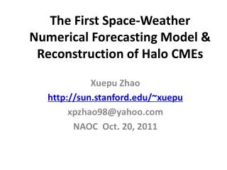
Specification of the broad shell of dense plasma for halo CMEs. Xuepu Zhao Stanford University EGU Session ST2 Vienna, Austria 25 April 2005. 1. Purpose of the work (1).

E N D
Specification of the broad shell of dense plasma for halo CMEs Xuepu Zhao Stanford University EGU Session ST2 Vienna, Austria 25 April 2005
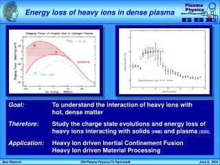
1. Purpose of the work (1) • Halo CMEs are interpreted as the Thompson scattering of a broad shell or bubble of dense CME electrons in the line of sight [Howard et al., 1982]. • For a conical shell of dense CME plasma we have developed a geometrical model, the cone model, to determine the angular width, direction of central axis and radial bulk speed for halo CMEs [Zhao, Plunkett & Liu, 2002].
1. Purpose of the work (2) • By imputing the properties obtained for the 12 May 1997 full halo CME into a MHD model of CME propagation, we can answer such questions as whether or not, which part of, and when the CME can hit the Earth [Odstrcil, Riley and Zhao, 2004]. • Recent UV observations show that most of halo CMEs are ice cream cone-like. This work improves the cone model for predicting the shape of halo CMEs formed by ice cream cone-like shell of dense CME plasma.
2. Cone models with round & elliptical cross sections • LT the cone • LB the small ICC. A sphere section with it’s center at apex • RT the large ICC. A half sphere sitting on top of a cone • RB the spherical C m. a sphere drop into a cone [Howard et al., 2002; Fisher & Munro, 1984; Schwenn et al., 2005]
2.1. The cone model with a round cross section (CS) Figure 2 For conical shells [Howard et al., 1982], the shape of halo CMEs can be produced by projecting the cross section of the cone on to the plane of the sky (POS)
Yh Z’c Smj Smn Ddc α Xh Figure 2.3 The four characteristic parameters of an ellipse: semi-major and semi-minor axes, Smj and Smn, and the distance of the ellipse’s center from Sun’s disk center, Ddc. Smn is parallel to Z’c & Ddc
= Z’c(The plan of the sky) Smj=rsinω Smn=rsinωsinθ r Zc(central axis) rcosω θ Ddc =rcosωcosθ μ ω Zh(LOS) Earth-directed if ω> μ= 90 - θ sinθ=Smn/Smj tanω=Smj cosθ/ Ddc=(Smj^2-Smn^2)^0.5/Ddc Figure 2.4 The relationship between Smj, Smn, Sdc and r, θ, ω.
Figure 2.5 Fitting the 6 Jan 1997 halo CME’s halos observed at various time with the ellipses calculated at corresponding r(t)
Figure 2.6 Fitting the r(t)-t scatter plot to infer the velocity & acceleration
2.2 The cone model with an elliptic cross section (CS) • We have shown that Smn is parallel to the projected cone axis for the round cone model. • The following shows an example of halo CMEs with Smj parallel to the projected cone axis, implying that the cross section must not be round.
Figure 2.7 Fitting the observed halos for the 7 April 1997 halo CME using the cone model with an elliptic cross section.
Figure 2.8 Fitting the r(t)-t scatter plot, and getting the velocity and acceleration.
3. Ice cream cone models with its front surface being a sphere section Ice cream cone models contain two parts. The cone part is the same as the cone model and produces an ellipse In POS. The ice cream part can produce only a half ellipse in the front side of the major axis, as shown in next slide.
Figure 3.1 The red ellipse is produced by the cone part, the front green & blue half ellipses are produced by small and large ice cream parts, respectively.
The ICC model Ddc = r cosω cosθ Smj = r sinω Smnc = r sinω sinθ Smni = r i cos θ The large ice cream part: Smj = r sinω Smni = r sin ω cosθ Smnc/Smni=1 => θ=45 The small ice cream part: Smj = r sinω Smni = r (1 - cos ω) cosθ Smnc / Smni=1 => tanθ= (1-cosω) / sinω ω=60,θ=30 3.1 Formulae for ice cream cone (ICC) models
Fig. 3.2a The projected ellipses calculated using cone model (red), small ICC model (green), and large ICC model (blue). ω=40, α=0, θ=0,10,17,19,21, 23,25,27,30,40,45,50,60,70,80,90 deg.
Fig. 3.2b The Same as Fig. 3.2a exceptα=20. Asθ increases, the front green and blue half ellipses decreses and the front red half ellipes increases. They become the same when θequals 22 and 45 degrees respectively.
Fig. 3.2c The same as Fig. 3.2a except α= 90 degrees. The projected ellipses for small and large ICC models can be reproduced using the cone model when θgreater than a critical value.
3.2 The shape of halo CMEs for small and large ICC shell of dense plasma • The shape depends on θ, the angle of the central axis from the POS. • The front half ellipse is greater than the rear half ellipse whenθ< 45 for the large ICC models, and the ellipes becomes symmetric when θ>= 45 deg. • When ω=60 &θ> 30, the ellipse is symmetric for small ICC model. Since the observational definition of halo CME is ω> 60, no difference between the cone and small ICC models. • The four parameters of the cone can be uniquely determined for ICC models.
4. Summary (1) A. Asymmetric elliptic halo CMEs with minor axes aligned with the projected central axis but the front semi-minor axis greater than the rear semi-minor axis are formed by the round ice cream conical shell of dense plasma. The five ICC properties can be uniquely determined using measured αangle, Ddc, Smj and the front & rear Smn.
4. Summary (2) B. Symmetric elliptic halo CMEs with minor axises aligned with the projected cone axis are formed by round conic or ice cream conic shell of dense CME plasma, and their angular width, direction of central axis and radial bulk speed can be uniquely determined using the cone model.
4. Summary (3) C. Symmetric elliptic halo CMEs with major axises aligned with the projected cone axis are formed by elliptic conic shell of dense CME plasma. The round halo CMEs with significant Ddc are formed by spheric cone. The properties for those halo CMEs can not be uniquely determined using the cone-like models.
4. Summary (4) D. Limb full halo CMEs with a significant Ddc are certainly not formed by Thompson scattering of Sun’s white light at very wide cone-like shell of dense plasma. The full halo may be formed by shock deflection of preexisting rays and streamers. Cone-like models cannot be used to reproduce such full halo CMEs.
4. Summary (5) E. The reliability of the determination for the geometrical and kinematical properties directly depends on the four elliptic parameters, Smj, Smn, Ddc and αangle. The shape of halo CMEs should be objectively determined. We plan to develop a software to do this job.
Pure ellipse in POS Smj = r sinω Smn = r sinω sinθ Ddc = r cosω cosθ α sinθ = Smn / Smj tanω=cosθSmj/Ddc r = Smj / sinω Inferences from C models a. Smn || projected cone axis b. Smn > Ddc, => ω > μ=90-θ=> Earth-directed if ω is constant c. Smn > Ddc + Rc2 => full halo d. The determination is unique for round CS & ununique for elliptic CS 2.3 What obtained from the round cone model
4. Summary (4) E. There are full halo-like CMEs associated with M- or X-class flares occurred near limbs. These full halo-like CMEs are called “limb full halo CMEs” [e.g., Schwenn et al., 2005]. The limb full halo CMEs usually are very fast, and most likely is formed due to the deflection of preexisting coronal features by superAlfvenic CMEs (St Cyr & Hundhausen, 1998). Such full halo CMEs usually have ragged spatial structure (Sheeley et al., 2000. Fig. 3a,b), which may be used to distinguish the “deflection-formed halo CME” from the “scattering-formed halo CME”.
Figure 4.1. The 25 July 1999 halo CME, an example of deflection-formed halo CME associated with a M-flare at N38W81 (see Sheeley et al., 2000)
Figure 4.2 The 4 Nov. 2003 halo CME, another example of deflection- formed halo CME. It is associated with a X28(45) flare at S22W88
3. Limb full halo CMEs (2) • The other interpretation for limb full halo CMEs is the Thompson scattering of Sun’s white light by a very WIDE cone-like bubble of dense CME electrons in the line of sight. • Since Smj = r sinω, Smn = r sinω sinθ Ddc = r cosω cosθ very wide & limb source implies small Ddc, Smn, as shown in next slide.
Figure 4.3 The halo CMEs formed by very wide cone-like shell of dense plasma. The half angular width ω= 89 deg, θ= 5, 10, 15, 30, 45, 60, 75, 90. The WIDE angular width interpretation does not work for the above two limb full halo CMEs